RT-SVX059D-EN 13
Unit Weights
Table 1. Maximum unit & corner weights (lb) and center of gravity dimensions (in.) cooling with optional electric heat
units only
Tons
Unit
Model No.
Weights (lb)
(a),
(a)Weights are approximate.
(b)
(b)Weights do not include additional factory or field installed options/accessories.
Corner Weights
(c)
(c) Corner weights are given for information only.
Center of Gravity (in.)
Shipping Net A B C D Length Width
3 EBC036* 542 492 90 102 159 141 41 29
4 EBC048* 570 520 104 108 157
152 39 28
5 EBC060*
590 540 113 112 157 158 38 28
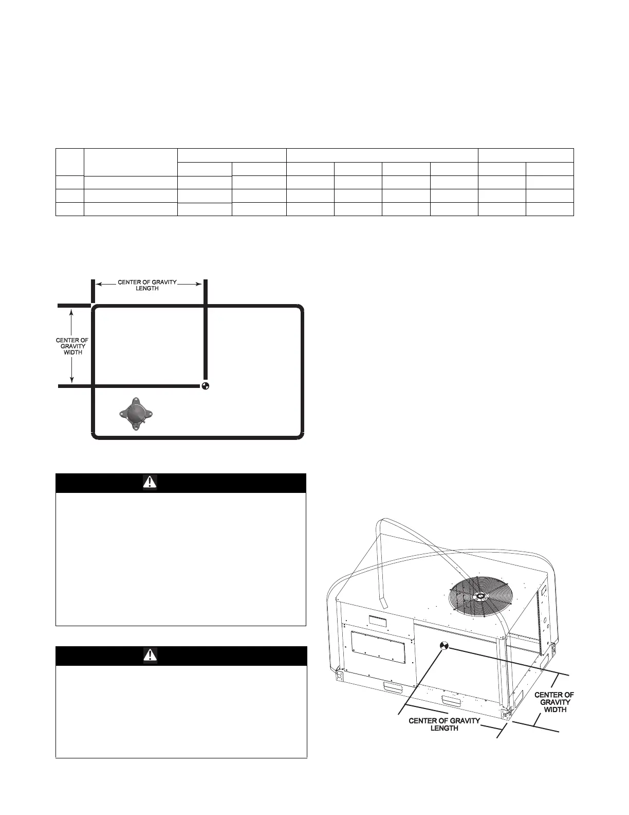
Figure 9. Corner weights
Rigging
WARNING
Heavy Objects!
Ensure that all the lifting equipment used is properly
rated for the weight of the unit being lifted. Each of the
cables (chains or slings), hooks, and shackles used to
lift the unit must be capable of supporting the entire
weight of the unit. Lifting cables (chains or slings) may
not be of the same length. Adjust as necessary for even
unit lift. Other lifting arrangements could cause
equipment or property damage. Failure to follow
instructions above or properly lift unit could result in
unit dropping and possibly crushing operator/
technician which could result in death or serious injury.
WARNING
Improper Unit Lift!
Test lift unit approximately 24 inches to verify proper
center of gravity lift point. To avoid dropping of unit,
reposition lifting point if unit is not level. Failure to
properly lift unit could result in unit dropping and
possibly crushing operator/technician which could
result in death or serious injury and possible equipment
or property-only damage.
Refer to Figure 10 an
d Table 1 for typical unit operating
weights rigging before proceeding.
2. Remove the shipping crate from around the unit. Do
n
ot remove the crating from the top of the unit.
3. Rig the unit as shown in Figure 10, p. 13. Attach
adequate s
trength lifting slings to all four lifting
brackets in the unit base rail. Do not use cables, chains,
or slings except as shown.
4. Install a lifting bar, as shown in Figure 10, to protect the
un
it and to facilitate a uniform lift. The minimum
distance between the lifting hook and the top of the
unit should be 7 feet.
5. Test-lift the unit to ensure it is properly rigged and
balanc
ed, make any necessary rigging adjustments.
6. Lift the unit and position it into place.
7. Downflow units; align the base rail of the
unit with the
curb rail while lowering the unit onto the curb. Make
sure that the gasket on the curb is not damaged while
positioning the unit.
Figure 10. Rigging and center of gravity