RT-SVX059D-EN 21
Maintenance
Make sure all personnel are standing clear of the unit
before proceeding. The system components will start
when the power is applied.
Fan Belt Adjustment—Belt Drive
Units
WARNING
Rotating Components!
The following procedure involves working with rotating
components. Disconnect all electric power, including
remote disconnects before servicing. Follow proper
lockout/tagout procedures to ensure the power can not
be inadvertently energized. Failure to disconnect power
before servicing could result in rotating components
cutting and slashing technician which could result in
death or serious injury.
The fan belts must be inspected periodically to assure
pr
oper unit operation.
Replacement is necessary if the belts appear frayed or
worn. Units with dual
belts require a matched set of belts
to ensure equal belt length.
When removing or installing the new belts, do not stretch
them
over the sheaves. Loosen the belts using the belt
tension adjustment bolts on the motor mounting base.
Once the new belts are installed, using a Browning or
G
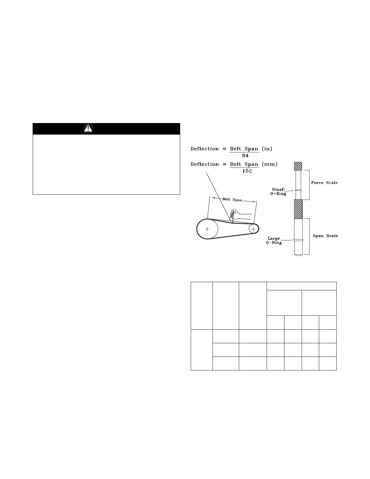
ates tension gauge (or equivalent) illustrated in
Figure 12; adjust the belt tension as follows;
1. To determine the appropriate belt deflection;
a. Measure the center-to-center shaft distance (in
in
ches) between the fan and motor sheaves.
b. Divide the distance measured in Step 1a by 64; the
r
esulting value represents the amount of belt
deflection that corresponds to the proper belt
tension.
2. Set the large O-ring on the belt tension gauge at the
de
flection value determined in Step 1b.
3. Set the small O-ring at zero on the force scale of the
ga
uge plunger.
4. Place the large end of the gauge at the center of the belt
spa
n; then depress the gauge plunger until the large
O-ring is even with the top of the next belt or even with
a straightedge placed across the fan and motor
sheaves.
Refer to Table 5, p. 21.
5. Remove the belt tension gauge. The small O-ring now
in
dicates a number other than zero on the plunger’s
force scale. This number represents the force (in
pounds) required to give the needed deflection.
6. Compare the “force” scale reading (Step 5) with the
appropriate “force” value listed in Table 5, p. 21. If the
“f
orce” reading is outside the range, readjust the belt
tension.
Note: Actual belt deflection “force
” must not exceed the
maximum “force” value shown in Table 5, p. 21.
7. Recheck the belt tension at least twice during the first
2
to 3 days of operation. Belt tension may decrease
until the new belts are “run in”.
Figure 12. Belt tension gauge
Table 5. Belt tension measurement and deflection
ranges
Belts
Cross
Section
Smallest
Sheave
Diameter
Range
(in.)
RPM
Range
Deflection Force (lb)
Super
Gripbelts and
Unnotched
Gripbands
Gripnotch
Belts and
Notched
Gripbands
Used
Belt
New
Belt
Used
Belt
New
Belt
A, AX
3.0–3.6
1000-2500
2501-4000
3.7
2.8
5.5
4.2
4.1
3.4
6.1
5.0
3.8–4.8
1000-2500
2501-4000
4.5
3.8
6.8
5.7
5.0
4.3
7.4
6.4
5.0–7.0
1000-2500
2501-4000
5.4
4.7
8.0
7.0
5.7
5.1
8.4
7.6