20 RT-SVX059D-EN
Start Up
Compressor Start-Up
1. Attach a set of service gauges onto the suction and
discharge gauge ports for each circuit. Refer to the
refrigerant circuit illustration in the Service Facts.
Using the Service Test Guide, pe
rform the proper test
mode connections.
Scroll Compressors
a. Once the compressor has started, verify that the
rotation is correct. If wired correctly the suction
pressure should drop and the discharge pressure
should rise. If a scroll compressor is rotating
backwards, it will not pump and a loud rattling
sound can be observed.
b. If the electrical phasing is correct, before
co
ndemning a compressor, interchange any two
leads (at the compressor Terminal block) to check
the internal phasing. Refer to the following
illustration for the compressor terminal/phase
identification. Do not allow the compressor to
operate backwards for more than 5 seconds.
Operation for a period of time longer than this will
result in compressor damage. Copeland (Alliance)
will experience failure also. If the compressor runs
backward for an extended period, the motor
winding can overheat and cause the motor winding
thermostat to open.
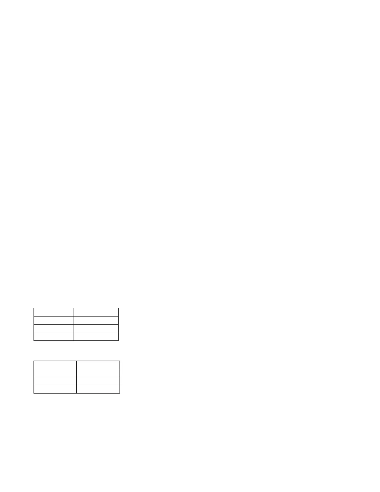
Note: T
he Copeland SXA scroll compressors for R-410A
units use Trane OIL00094. Compressor types are
listed in Table 3, p. 20. The appropriate oil charge is
li
sted in Table 4, p. 20.
Table 3. Compressor types
Tonnage C1
EBC036 SXA039
EBC048 SXA051
EBC060 SXA057
Table 4. POE Oil recharge amount (fl. oz.)
Model C1
EBC036 38
EBC048 38
EBC060 38
2. After the compressor and condenser fan have started
and operated for approximately 30 minutes, observe
the operating pressures. Compare the operating
pressures to the operating pressure curve in the
Service Facts.
3. Check system subcooling. Foll
ow the instruction listed
on the subcooling charging curve in the Service Facts.
4. Repeat Step 1 through Step 3 for each refrigerant
circuit.
5. To stop the SERVICE TEST
, turn the main power
disconnect switch to the “Off” position or proceed to
the next component start-up procedure. Remove
electro mechanical test mode connections (if
applicable).
Heating Start-Up
1. Clamp an amp meter around one of 1
st
stage heater
power wires at the heater contactor.
2. Verify that the heater stage is operating properly.
3. Clamp an amp meter around one of 2
nd
stage heater
power wires at the heater contactor (if applicable).
4. Verify that the heater stage is operating properly.
5. To stop the SERVICE TEST
, turn the main power
disconnect switch to the “Off” position or proceed to
the next component start-up procedure. Remove
electro mechanical test mode connections.
Final System Set Up
After completing all of the pre-start and start-up
procedures outlined in the previous sections (i.e.,
operating the unit in each of its modes through all
available stages of cooling and heating), perform these
final checks before leaving the unit:
• Program the Night Setback (NSB) panel (if applic
able)
for proper unoccupied operation. Refer to the
programming instructions for the specific panel.
• Verify that the Remote panel “System” selection
switch
, “Fan” selection switch, and “Zone
Temperature” settings for automatic operation are
correct.
• Inspect the unit for misplaced tools, hardware, and
de
bris.
• Verify that all exterior panels including the control
pa
nel doors and condenser grilles are secured in place.
• Close the main disconnect switch or circuit protector
switc
h that provides the supply power to the unit’s
terminal block or the unit mounted disconnect switch.