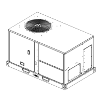
Installation
RT-SVX059D-EN 15
Main Electrical Power Requirements
• Verify that the power supply complies with the unit
nameplate specifications.
• Inspect all control panel components; tighten any
lo
ose connections.
• Connect properly sized and protected power supply
wiring to a field-su
pplied/ installed disconnect switch
and to the main power terminal block (HTB1) in the unit
control panel.
• Install proper grounding wires to an earth ground.
Note: Al
l field-installed wiring must comply with NEC
and applicable local codes.
Electric Heat Requirements
• Verify that the power supply complies with the electric
heater specifications on the unit and heater nameplate.
• Inspect the heater junction box and control panel;
tig
hten any loose connections.
• Check electric heat circuits for
continuity.
• Low Voltage Wiring (AC and DC) Requirements
• Install the zone thermostat, w
ith or without switching
subbase.
• Connect properly sized control wiring to the proper
te
rmination points between the zone thermostat and
the unit control panel.
Condensate Drain Configuration
An evaporator condensate drain connection is provided
on each unit. Refer to the unit overview figure in
“Dimensional Data,” p. 8 for the appropriate drain
location.
Note: Don
't use PVC glue to connect condensate drain.
Thread sealing compound or Teflon tape may be
used.
A condensate trap must b
e installed at the unit due to the
drain connection being on the “negative pressure” side of
the fan.
A condensate drain line must be connected
to the P-Trap.
Pitch the drain lines at least ½-inch for every 10 feet of
horizontal run to assure proper condensate flow. Do not
allow the horizontal run to sag causing a possible double-
trap condition which could result in condensate backup
due to “air lock”.
Filter Installation
Each unit ships with 2-inch filters installed. The quantity of
filters is determined by unit size. Access to the filters is
obtained by removing the filter access panel.
Refer to the unit Service Facts
(shipped with each unit) for
filter requirements.
Note: Do not operat
e the unit without filters.
Field Installed Power Wiring
An overall dimensional layout for the standard field
installed wiring entrance into the unit is illustrated in
“Dimensional Data,” p. 8. To insure that the unit’s supply
po
wer wiring is properly sized and installed, follow the
guidelines outlined below.
Note: All
field installed wiring must conform to NEC
guidelines as well as state and Local codes.
Verify that the power supply available is compatible with
the
unit’s nameplate ratings. The available supply power
must be within 10 percent of the rated voltage stamped on
th
e nameplate. Use only copper conductors to connect the
power supply to the unit.
NOTICE
Use Copper Conductors Only!
Unit terminals are not designed to accept other types of
conductors. Failure to use copper conductors could
result in equipment damage.
Note: If the unit is not equipped with an optional factory
installed nonfused disconnect switch or circuit
breaker, a field supplied disconnect switch must be
installed at or near the unit in accordance with the
National Electrical Code (NEC latest edition).
Main Unit Power
WARNING
Proper Field Wiring and Grounding
Required!
All field wiring MUST be performed by qualified
personnel. Improperly installed and grounded field
wiring poses FIRE and ELECTROCUTION hazards. To
avoid these hazards, you MUST follow requirements for
field wiring installation and grounding as described in
NEC and your local/state electrical codes. Failure to
follow code could result in death or serious injury.
Standard Wiring
The electrical service must be protected from over current
and short circuit conditions in accordance with NEC
requirements.
Protection devices must be sized
according to the
electrical data on the nameplate.
• If the unit is not equipped with
an optional factory
installed nonfused disconnect switch, a field supplied
disconnect switch must be installed at or near the unit
in accordance with the National Electrical Code (NEC
latest edition).
• Location of the applicable electrical service entrance is
ill
ustrated in “Dimensional Data,” p. 8. Complete the
un
it’s power wiring connections onto either; the main
terminal block HTB1 inside the unit control panel, the