Installation
16 RT-SVX059D-EN
factory mounted nonfused disconnect switch (UCD),
or the electric heat terminal block. Refer to the
customer connection diagram that shipped with the
unit for specific termination points.
• Provide proper grounding for the unit in accordance
with local
and national codes.
Control Power Transformer
The 24-volt control power transformers are to be used only
with the accessories called out in this manual.
Transformers rated greater than 50 Vac are equipped with
internal circuit breakers. If a circuit breaker trips, turn “Off”
all power to the unit before attempting to reset it.
The transformer is located in the control panel. The circuit
br
eaker is located on the left side of the transformer and
can be reset by pressing in on the black reset button.
Controls Using 24 Vac
Before installing any connecting wiring, refer to
“Dimensional Data,” p. 8 for the electrical access locations
provided on the unit and Table 2, p. 16 for AC conductor
sizing guidelines.
NOTICE
Use Copper Conductors Only!
Unit terminals are not designed to accept other types of
conductors. Failure to use copper conductors could
result in equipment damage.
1. Use copper conductors unless otherwise specified.
2. Ensure that the AC control wiring between the controls
an
d the unit’s termination point does not exceed three
(3) ohms/conductor for the length of the run.
Note: Resis
tance in excess of 3 ohms per conductor could
cause component failure due to insufficient AC
voltage supply.
3. Be sure to check all loads an
d conductors for grounds,
shorts, and mis-wiring.
4. Do not run the AC low voltag
e wiring in the same
conduit with the high voltage power wiring.
5. Route low voltage wiring per illustrations on the
next
page.
Table 2. Electromechanical t
hermostat 24 Vac
conductors
Distance from Unit to
Control Recommended Wire Size
000–460 feet 18 gauge
000–140 m 0.75 mm
2
461–732 feet 16 gauge
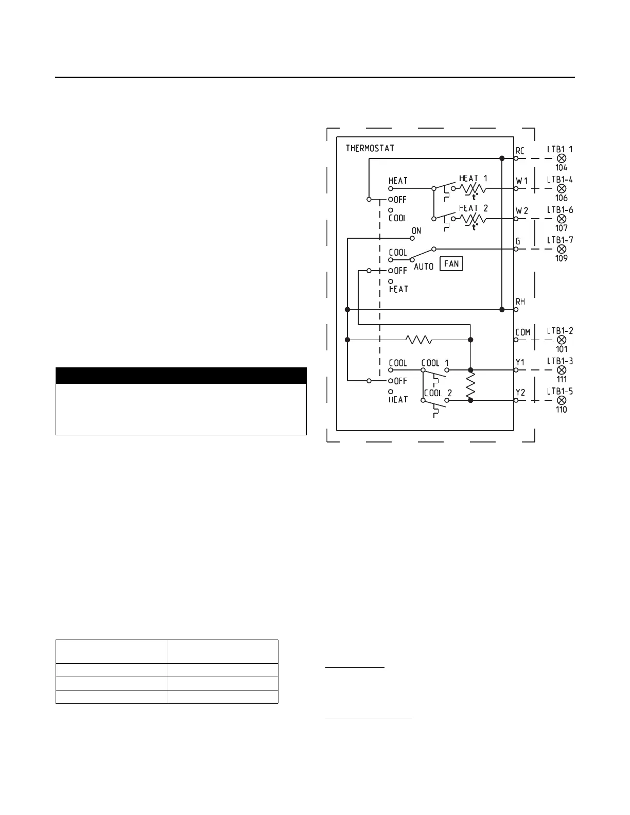
Figure 11. Conventional thermostat field wiring
diagram
Voltage Imbalance
Three phase electrical power to the unit must meet
stringent requirements for the unit to operate properly.
Measure each leg (phase-to-phase) of the power supply.
Each reading must fall within the utilization range
stam
ped on the unit nameplate. If any of the readings do
not fall within the proper tolerances, notify the power
company to correct this situation before operating the
unit.
Excessive three phase voltage imbalance between phases
will
cause motors to overheat and eventually fail.
The maximum allowable voltage imbalance is 2 percent.
M
easure and record the voltage between phases 1, 2, and
3 and calculate the amount of imbalance as follows:
% Voltage Imbalance =
100 X AV - VD
where;
AV
AV (Average Voltage) =
Volt 1 + Volt 2 + Volt 3
3
• V1, V2, V3 = Line Voltage Readings