RT-SVX059D-EN 25
Wiring Diagrams
Note: Wiring diagrams can be accessed via e-Library by
entering the diagram number in the literature order
number search field or by contacting technical
support.
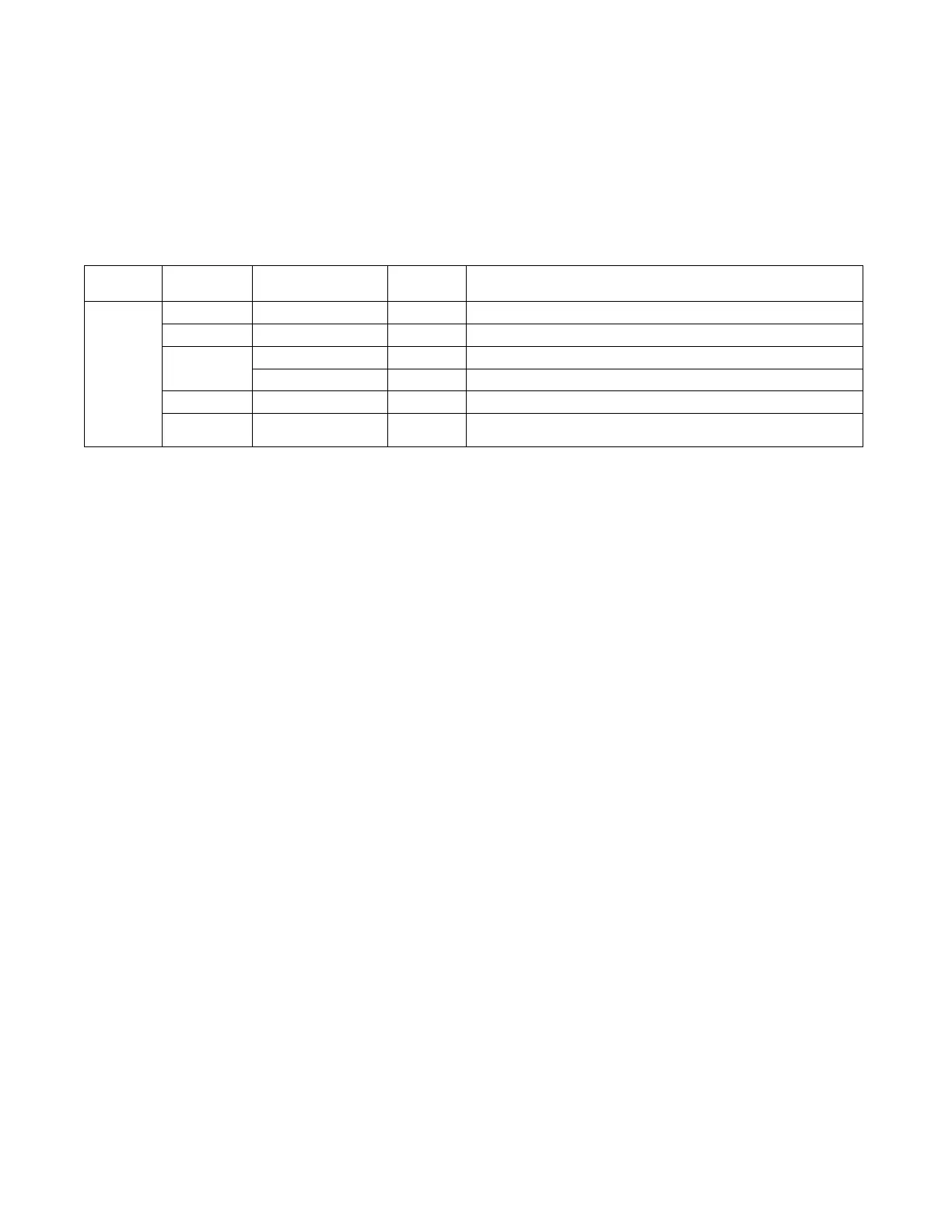
Table 7. Wiring diagrams
Type of
Airflow
Schematic
Type Voltage
Diagram
Number Description
Constant
Volume
Power 380-415 12130801 Cooling only
Control 380-415 12132964 Cooling only
Control Box
C
onnection
380-415 12131531 Electric Heat-208/575- 5-15KW
380-415 12131533 Electric Heat-460/575-20-25KW
Connection 380-415 12133022 Cooling only
Raceway
C
onnection
380-415 12131609 Cooling only