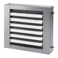
Dimensions
and Weights
CAB-PRC001-EN 37
Horizontal Cabinet, Model D
Horizontal cabinet unit dimensions & weights, in-lbs.
unit
size 02-03 04 06 08 10-12
A 2’-9
5
/16 3’-2
5
/16 3’-11
13
/16” 4’-8
5
/16” 6’-3
5
/16”
B 1’-9
5
/16 2’-2
5
/16 2’-11
13
/16” 3’-8
5
/16” 5’-3
5
/16”
C7
5
/8 7
1
/8 8
7
/8”7
1
/8”7
5
/8
D 1’-6” 2’-0” 2’-6 3’-6 5’-0
E 1’-7
5
/16” 2’-0
5
/16” 2’-9
13
/16 3’-6
5
/16 5’-1
5
/16
F 3’-5
5
/16” 3’-10
5
/16” 4’-7
3
/16 5’-4
5
/16 6’-11
5
/16
G8
5
/8”8
1
/8”9
1
/8”8
1
/8”8
5
/8”
H 1’ -4” 1’ -10” 2’ -4” 3’ -4” 4’ -10”
J 1’ -7
3
/4” 1’ -11
3
/4” 2’ -7
3
/4” 3’ -3
3
/4” 4’ -11
3
/4”
operating weight 97 125 155 164 218
shipping weight 84 112 139 148 200
Note: 1. Coil connections are always on the side opposite the control box.
2. Coil connections are
5
/8” O.D. sweat. See page 44 for locations.
3. All duct collar dimensions are to the outside of the collar.
4. See page 45 for fresh air opening dimensions.
 Loading...


