26
RT-SVX094A-EN
Standard Wiring
The electrical service must be protected from over current
and short circuit conditions in accordance with NEC
requirements.
Protection devices must be sized according to the electrical
data on the nameplate.
• If the unit is not equipped with an optional factory
installed nonfused disconnect switch, a field supplied
disconnect switch must be installed at or near the unit
in accordance with the National Electrical Code (NEC
latest edition).
• Location of the applicable electrical service entrance is
illustrated in “Dimensional Data,” p. 10. Complete the
unit’s power wiring connections onto either; the main
terminal block HTB1 inside the unit control panel, the
factory mounted nonfused disconnect switch (UCD), or
the electric heat terminal block. Refer to the customer
connection diagram that shipped with the unit for
specific termination points.
• Provide proper grounding for the unit in accordance
with local and national codes. See Table 5, p. 26 for
ground wire torque.
Table 5. Ground wire torque
Ground wire size
(AWG)
Torque (in-lbs)
10 - 14 35
8 40
4 - 6 45
2/0 - 0 50
Optional TBUE Wiring (Through-the-
Base Electrical Option)
• Location of the applicable electrical service is illustrated
below. Refer to the customer connection diagram that
is shipped with the unit for specific termination points.
The termination points, depending on the customer
option selected would be a factory mounted nonfused
disconnect switch (UDC).
• Provide proper grounding for the unit in accordance
with local and national codes. See Table 6, p. 26 for
ground wire torque.
Table 6. Ground wire torque
Ground wire size (AWG) Torque (in-lbs)
10 - 14 35
8 40
Table 6. Ground wire torque (continued)
Ground wire size (AWG) Torque (in-lbs)
4 - 6 45
2/0 - 0 50
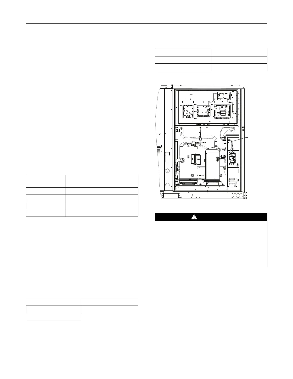
Figure 13. Through-the-base electrical option
ELECTRO MECHANICAL
TBU FIELD WIRING.
ROUTE FIELD WIRING
AS SHOWN.
Control Power Transformer
WARNING
Hazardous Voltage!
Failure to disconnect power before servicing could
result in death or serious injury.
Disconnect all electric power, including remote
disconnects before servicing. Follow proper lockout/
tagout procedures to ensure the power can not be
inadvertently energized. Verify that no power is
present with a voltmeter.
The 24-volt control power transformers should be used
only with the accessories called out in this manual.
Transformers rated greater than 50 VA are equipped with
internal circuit breakers. If a circuit breaker trips, turn OFF
all power to the unit before attempting to reset it.
The transformer is located in the control panel. The circuit
breaker is located on the left side of the transformer and
can be reset by pressing in on the black reset button.
Installation