34
RT-SVX094A-EN
Start-Up
Symbio 700 Controls –
Sequence of Operation
These units are offered with Symbio™ 700 controls.
Refer to Symbio 700 Controller with Foundation Packaged
Rooftop Units 15 to 25 Tons Application Guide (ACC-
APG004*-EN) for more details on sequence of operation.
Compressor Start-Up
1. Attach a set of service gauges onto the suction and
discharge gauge ports for each circuit. Refer to the
refrigerant circuit illustration in the Service Facts.
Scroll Compressors
a. Once each compressor has started, verify that the
rotation is correct. If wired correctly the suction
pressure should drop and the discharge pressure
should rise. If a scroll compressor is rotating
backwards, it will not pump and a loud rattling
sound can be observed.
b. If the electrical phasing is correct, before
condemning a compressor, interchange any two
leads (at the compressor Terminal block) to check
the internal phasing. Refer to the following
illustration for the compressor terminal/phase
identification. Do not allow the compressor to
operate backwards for more than 5 seconds.
Operation for a period of time longer than this will
result in compressor damage.
Note: Copeland YA scroll compressors for R-454B
units use Trane OIL00094. Compressor types
and appropriate oil charge is listed in the
following tables.
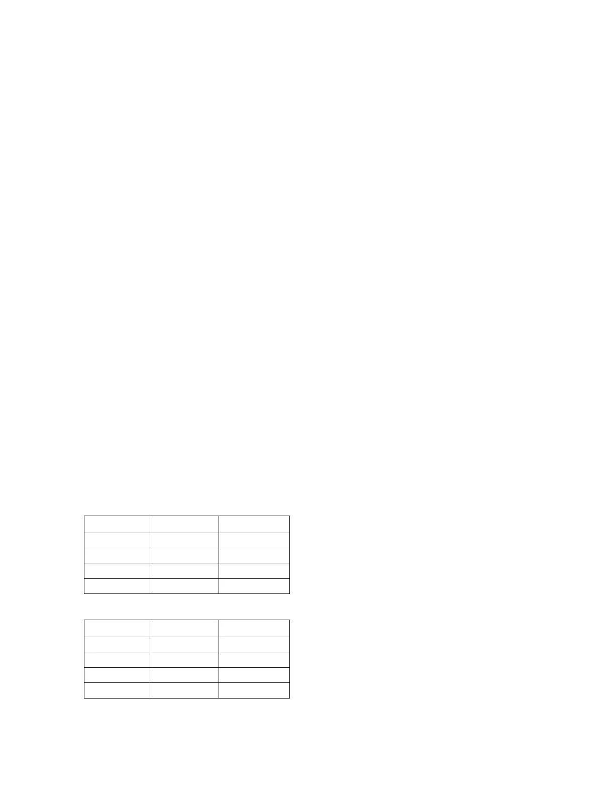
Table 11. Compressor types
Tonnage Compressor 1 Compressor 2
EDK180 YA104K1E* YA51K1E*
EDK210 YA122K1E* YA61K1E*
EDK240 YA137K1E* YAS76K1E*
EDK300 YA154K1E* YAS91K1E*
Table 12. POE Oil recharge amount (fl. oz.)
Tonnage Compressor 1 Compressor 2
EDK180 81 36
EDK210 81 36
EDK240 118 54
EDK300 118 54
2. After the compressor and condenser fan have started
and operated for approximately 30 minutes, observe
the operating pressures. Compare the operating
pressures to the operating pressure curve in the
Service Facts.
3. Check system subcooling. Follow the instruction listed
on the subcooling charging curve in the Service Facts.
4. Repeat Step 1 through Step 3 for each refrigerant
circuit.
5. To stop the SERVICE TEST, turn the main power
disconnect switch to the OFF position or proceed to the
next component start-up procedure. Remove
electromechanical test mode connections (if
applicable).
Heating Start-Up
1. Clamp an amp meter around one of 1
st
stage heater
power wires at the heater contactor.
2. Verify that the heater stage is operating properly.
3. Clamp an amp meter around one of 2
nd
stage heater
power wires at the heater contactor (if applicable).
4. Verify that the heater stage is operating properly.
5. To exit Service Test Mode, choose the "Inactive"
service test step. Once Service Test is terminated, a
system reset occurs and the unit reverts to the normal
system control.
Final System Setup
After completing all of the pre-start and start-up procedures
outlined in the previous sections (i.e., operating the unit in
each of its modes through all available stages of cooling
and heating), perform these final checks before leaving the
unit:
☐ Program the Night Setback (NSB) panel (if applicable)
for proper unoccupied operation. Refer to the
programming instructions for the specific panel.
☐ Verify that the Remote panel “System” selection switch,
“Fan” selection switch, and “Zone Temperature”
settings for automatic operation are correct.
☐ Inspect the unit for misplaced tools, hardware, and
debris.
☐ Verify that all exterior panels including the control panel
doors and condenser grilles are secured in place.
☐ Close the main disconnect switch or circuit protector
switch that provides the supply power to the unit’s
terminal block or the unit mounted disconnect switch.