30
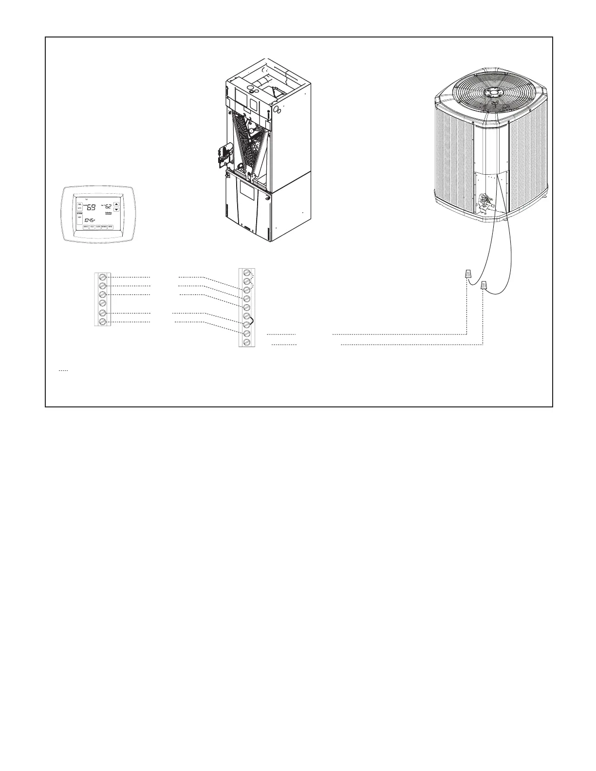
STEP 4 - Make connections per hookup diagrams.
Air Handler Hook-up Diagram
Cooling
Red
Yellow
Green
White
Blue
Yellow
Green
White
Blue
B
B - Blue
Blue
W
G
Y
Y - Yellow
Yellow
R
Red
O
Orange
Comfort Control
Air Handler
Air Conditioner
Field wiring
O **
R **
B
YI
W1
YO
G
W2
W3
* For multiple stages of electric heat, jumper W1, W2, and W3 together if comfort control has only one stage of heat. •
** R to • O jumper must be in place as shown for cooling only, non-heat pump systems for proper operation.
YI and YO connections must be made as shown for freeze protection and internally mounted condensate overflow circuits to work properly. •
Internally mounted condensate switch is optional and must be ordered separately. •
If 3rd party condensate overflow switches are installed, they should be wired in series between YO and Y to the outdoor unit. •
 Loading...