130 UV-PRC001-EN
End Device Controls
An end device control option shall
utilize factory selected control
components to allow other control
vendors to easily interface with a
classroom air conditioning unit.
The factory supplied components
shall be installed in the unit venti-
lator and wired to a terminal strip
before shipment. The following
options shall be selectable with
end device controls:
• Valve control
• Face and bypass control
• Low limit thermostat
• 24 volt transformer
• Fan start/stop relay
• 10 pole terminal block for field
hook-up
Filters
Each unit shall be equipped with a
single 1-inch thick, throwaway or
permanent, filter accessible with-
out removal of the unit front panel.
Units that contain a dynamic air
option, shall provide access to the
filters through the unit front panel.
See page 38 for filter location.
Shelving and Accessories
Unit ventilator shelving shall be
manufactured from 16-gauge cab-
inet steel and painted in decorator
colors as specified by the architect.
Shelving shall be equipped with
adjustable shelves reinforced with
a formed channel for maximum
strength. Closed shelving doors
shall be equipped with a locking
device.
The unit ventilator shelving shall
be equipped with a decorative and
protective Formica
TM
tops avail-
able in twelve colors. Shelving op-
tions shall include:
• Matching grilles
• Dynamic air barrier shelving
• Cut-to-fit filler section
• Piping compartment
Shelving shall be equipped with
leveling legs and hardware re-
quired to mate-up with the class-
room unit ventilator.
Sidewall Power Exhaust
A sidewall power exhaust shall be
provided with a cabinet similar to
the unit ventilator. The cabinet
shall be constructed of 16-gauge
steel with adjustable leveling legs
at four corners. The front panel
shall be constructed of 16-gauge
steel and secured by three cam-
lock fasteners. The exhaust unit
shall provide a nominal 500 or 750
cfm with a two speed switch. All
motors shall be 115/60/1 voltage
with direct drive fan(s).
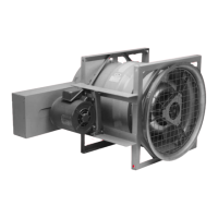
Energy Recovery Unit
The energy recovery heat ex-
changer shall be constructed to
have two separate air streams
flowing in counter flow configura-
tion. The heat exchanger shall
have a minimum effectiveness of
75 percent enthalpy energy ex-
change. Sensible energy only heat
recovery is not acceptable.
Energy recovery heat exchanger
shall be maintenance free and rat-
ed for the life of the unit. Units uti-
lizing rotating wheel heat
exchanger design shall have a self-
adjusting belt drive and motor(s)
with permanently lubricated bear-
ings.
Units shall not require a defrost
heater for operation with outside
air temperatures above the frost
threshold temperature dependent
on the winter room relative humid-
ity (RH) of:
1. 5 degrees F at 30% RH.
2. 10 degrees F at 40% RH.
3. 15 degrees F at 50% RH.
Units provided with outside air
damper must have factory mount-
ed damper actuator.
Units without electric defrost shall
receive power from space me-
chanical air conditioning unit for
all unit functions including fan mo-
tors and controls. Energy recovery
units with separate power source
shall include warning labels indi-
cating that more than one discon-
nect is required to disable all
power to air conditioning units
The units shall be interlocked with
space mechanical air conditioning
units to ensure space ventilation
during all occupied periods.
Wall boxes
Trane wall boxes shall provide
year-around moisture free, out-
door air intake directly to the unit
ventilator through the exterior
classroom wall. Wall boxes shall
be available in six standard ar-
rangements to meet installation
requirements on virtually any type
of building construction.
All Trane wall boxes shall be con-
structed of extremely heavy gauge
material and designed to last the
life of the building. Internal parts
shall be interlocked in addition to
being held securely in place by the
frame-within-a-frame design. This
assures proper louver alignment.
In addition, the strength of the ver-
tical louver design shall simplify
installation by eliminating the
need for a lintel. Wall boxes shall
contain a 1/2-inch square mesh
galvanized screen on the inside of
the louver.
Gravity Relief Dampers
The gravity relief dampers shall be
barometrically operated, alumi-
num bladed designed to be used
with each Trane unit ventilator.
The gravity relief damper shall be
provided with optional wall boxes.
Mechanical
Specifications
 Loading...


