28 UV-PRC001-EN
Filter Maintenance
Filter status for the controller is
based on the cumulative run hours
of the unit fan. The controller com-
pares the amount of fan run time
against an adjustable fan run hour
(stored in the controller) to deter-
mine when maintenance is recom-
mended for the unit. The run-
hours value may be user edited as
required (through Rover). The val-
id range for the fan run hours limit
is 0 to 5000 hours with a default of
600 hours. Once the run hours lim-
it has been exceeded, the control-
ler generates a maintenance
required diagnostic (unit will not
shut-down). The user will be noti-
fied of this diagnostic through the
building automation system or
when a Trane Service Tool is com-
municating with the controller.
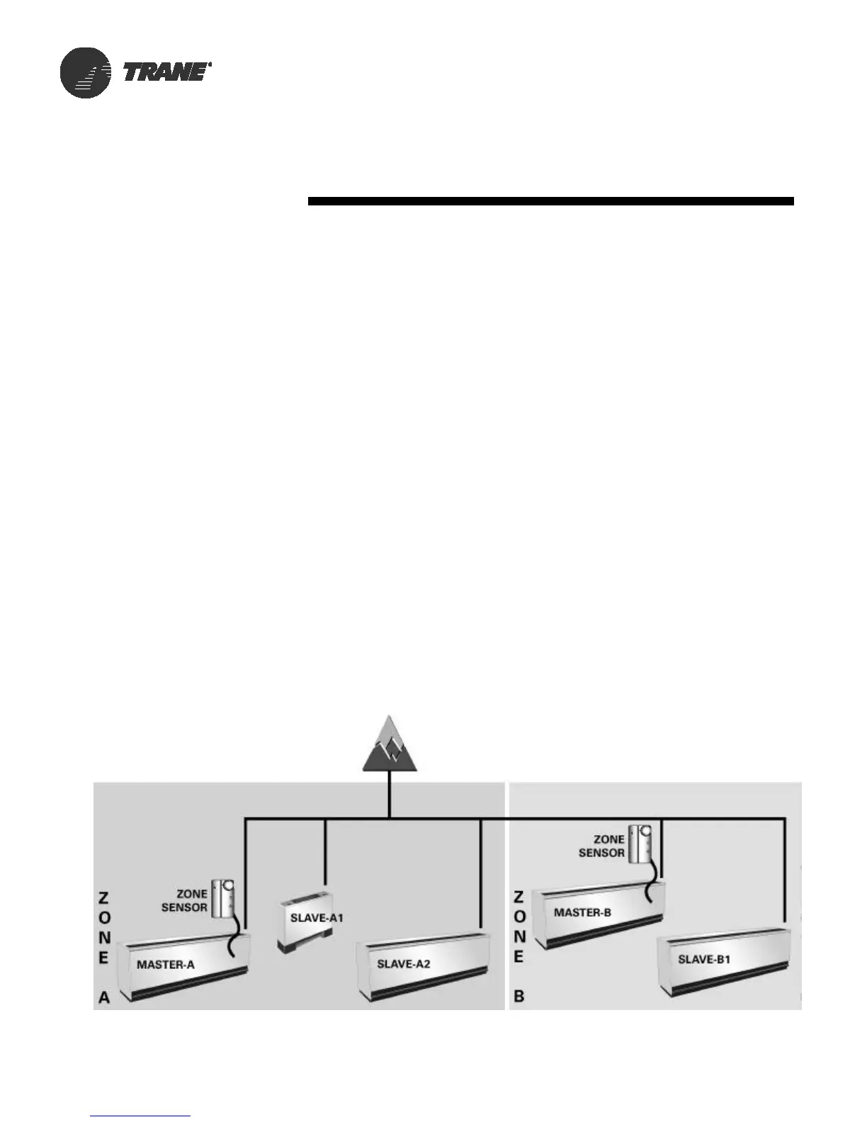
Master Slave
(Data Sharing)
Because the ZN520 controller uti-
lizes LonWorks
TM
technology, the
controller can send or receive data
(setpoint, heat/cool mode, fan re-
quest, space temperature, etc.) to
and from other controllers on the
communication link with or with-
out the existence of a building au-
tomation system. This applies to
applications where multiple units
might share one zone sensor for
both stand-alone (with communi-
cation wiring between units) and a
building automation system. See
Figure 27 for ZN520 master
slave system layout.
Controls
Tracer ZN520
Manual Output Test
The ZN520 controller includes a
manual output test function. This
function may be initiated from the
blue test push button on the con-
troller or through Rover
TM
. This
feature is used to manually exer-
cise the outputs in a defined se-
quence.
The purpose of this test sequence
is to verify output and end device
operation. The manual output test
function may also be used in the
following situations:
• Reset latching diagnostics
• Verify output wiring and op-
eration
• Force the water valve(s) open
to balance the hydronic sys-
tem during installation set-
up or service.
Figure 27: ZN520 master slave system