UV-PRC001-EN 9
Hydronic Main Coils
Hydronic Main Coils
All hydronic coils are wavy plate
finned and available in varied ca-
pacities (Table 5 and 6 listed be-
low). The coils are hydrostatically
tested at 350 PSI.
Piping packages for the main coil
assembly are always supplied as a
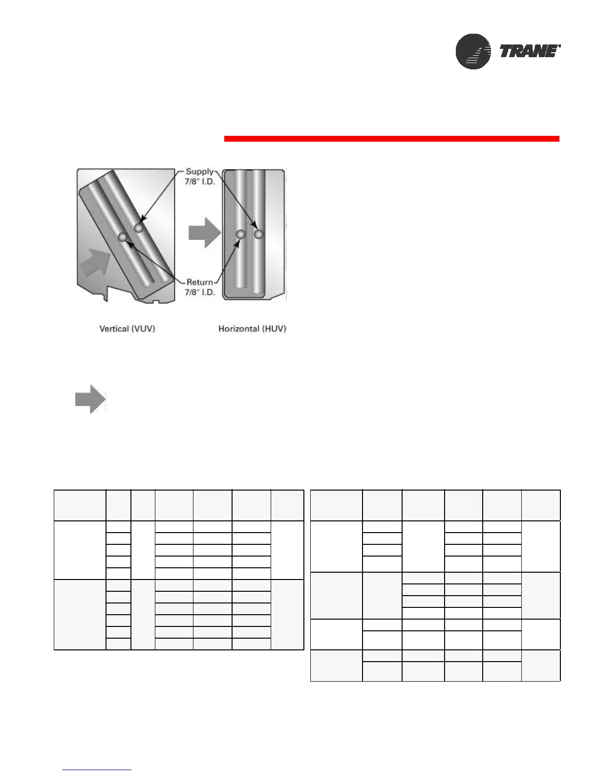
3/4-inch package. See Figure 11
for main coil header sizing for
2-pipe and 4-pipe systems.
Left hand configuration
shown.
Table 5: Single coil (2-pipe) data
Coil
Description
Coil
Type
Unit
Size
Fins per
inch FPI
Rows
Cooling
(main)
Rows
Heating
(main)
Face
&
Bypass
HW/CW
Main
Changeover
Coil
AA 12 2 2
H&V
AB 16 2 2
AC 12 3 3
AD 12 4 4
AE 16 4 4
HW ONLY
Main
Coil
H1 12 0 1
H&V
H2 14 0 1
H3 16 0 1
H4 12 0 2
H5 14 0 2
H6 16 0 2
Figure 11: Main coil header sizing for 2-
pipe and 4-pipe systems. (Left
hand configuration shown.)
Indicates air flow
075-200075-200
Table 6: Coupled coil (4-pipe) data
Coil
Description
Coil
Type
Unit
Size
Fins per
inch FPI
Rows
Cooling
(main)
Face
&
Bypass
CW-Main
HW-Preheat
Auxiliary
Coil
DA
075-200
12 2
H&V
DC 16 2
DD 12 3
DE 16 3
CW-Main
E-Heat-Aux.
Coil
X3-X6
075-100 12 3
Not
Available
125 16 2
150 12 3
200 16 3
CW-Main
Steam-Aux.
Coil
DK 075-150 12 3 Not
Available
DK 200 12 3
CW-Main
HW (reheat)-
Aux. Coil
R1 075-200 12 3 Not
Available
R2 075-200 16 3