LPC-SVX01C-EN 11
Installation
general
information
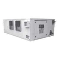
Packaged Climate Changer Model Number Description
Following is a complete description of the Packaged Climate Changer model number. Each digit in the model number has a
corresponding code that identifies specific unit options.
LPC A A 08 F 2 F0 L L B 0 0 000 0 0 A F B H B 0 0 0 0 0 0 0 0 0 0 0
1,2,3 4 5 6,7 8 9 10,11 12 13 14 15 16 17,18,19 20 21 22 23 24 25 26 27 28 29 30 31 32 33 34 35 36 37
Digit 13 - Unit Coil #1 Type (1st in Air Stream)
0 = no unit coil #1
hydronic heat coils
A = 1-row, 9 fpi
B = 1-row, 12 fpi
C = 1-row, 14 fpi
D = 2-row, 9 fpi
E = 2-row, 12 fpi
F = 2-row, 14 fpi
chilled hydronic coils
G = 4-row, 9 fpi
H = 4-row,12 fpi
J = 4-row, 14 fpi
K = 6-row, 9 fpi
L = 6-row, 12 fpi
M = 6-row, 14 fpi
N = 8-row, 9 fpi
P = 8-row, 12 fpi
R = 8-row, 14 fpi
DX coils,
3
/
16
” distributor
T = 4-row, 9 fpi
U = 4-row, 12 fpi
V = 4-row, 14 fpi
Steam Coil
1 = 1-row, 6 fpi
DX coils,
1
/
4
” distributor
5 = 6-row, 9 fpi
6 = 6-row DX, 12 fpi
7 = 6-row DX, 14 fpi
Digit 14 - Unit coil #2 type (2nd in air
stream)
0 = no unit coil #1
hydronic reheat coils
A = 1-row, 9 fpi
B = 1-row, 12 fpi
C = 1-row, 14 fpi
D = 2-row, 9 fpi
E = 2-row, 12 fpi
F = 2-row, 14 fpi
chilled hydronic coils
G = 4-row, 9 fpi
H = 4-row,12 fpi
J = 4-row, 14 fpi
K = 6-row, 9 fpi
L = 6-row, 12 fpi
M = 6-row, 14 fpi
DX coils,
3
/
16
” distributor
N = 4-row, 9 fpi
P = 4-row, 12 fpi
R = 4-row, 14 fpi
steam coil
W = 1-row, 6 fpi
DX coils,
1
/
4
” distributor
2 = 6-row, 9 fpi
3 = 6-row, 12 fpi
4 = 6-row, 14 fpi
Digit 1, 2, 3 - Unit model
LPC = Packaged Climate Changer
Digit 4 - Development sequence
A = “A” development sequence
Digit 5 - Configuration
A = horizontal/front top
B = horizontal/top front
C = vertical/front top
D = vertical/top front
E = vertical/back top
F = vertical/top back
Digit 6, 7 - Unit size
03 = 3 square feet of coil
06 = 6 square feet of coil
08 = 8 square feet of coil
10 = 10 square feet of coil
12 = 12 square feet of coil
14 = 14 square feet of coil
17 = 17 square feet of coil
21 = 21 square feet of coil
25 = 25 square feet of coil
30 = 30 square feet of coil
Digit 8 - Unit voltage
0 = no motor, controls, electric heat
A = 208/60/1
B = 230/60/1
C = 277/60/1
D = 208/60/3
E = 230/60 /3
F = 460/60/3
G = 575/60/3
H = 380/50/3
J = 415/50/3
Digit 9 - Insulation & Isolation
1 = 1 inch, matt faced
2 = 1 inch, foil faced
3 = 1 inch, double-wall with field provided
external isolaiton
4 = 1 inch, double-wall with internal
isolation
Digit 10,11 - Design sequence
Digit 12 - Drain pan type, coil & motor
connection location
R = polymer drain pan, RH coil & motor
L = polymer drain pan, LH coil & motor
C = polymer drain pan, RH coil & LH motor
D = polymer drain pan, LH coil & RH motor
E = SS drain pan, RH coil & motor
F = SS drain pan, LH coil & motor
G = SS drain pan, RH coil & LH motor
H = SS drain pan, LH coil & RH motor
Digit 15 - Access section (preheat)
0 = none
hydronic coils
A = 1-row, 9 fpi
B = 1-row, 12 fpi
C = 1-row, 14 fpi
D = 2-row, 9 fpi
E = 2-row, 12 fpi
F = 2-row, 14 fpi
G = 1-row steam coil, type NS, 6 fpi
R = no coil, matt face insulation
Digit 16 - Electric heat, factory mounted
only
0 = none
1 = electric heat with 1 stage
2 = electric heat with 2 stages
4 = electric heat with 4 stages
Digit 17, 18, 19 - Electric heater kW
006 - 018 = 1 kW increments
020 - 038 = 2 kW increments
041 - 059 = 3 kW increments
063 - 095 = 4 kW increments
95 and < = 5 kW increments
Digit 17, 18, 19 - Electric heater kW
Digit 20 - Control type
0 = none
1 = control interface
2 = Tracer AH540 zone temp. control
3 = Tracer AH540 discharge temp. control
Digit 21 = Electric heater options
0 = none
A = line fuse
B = door interlocking disconnect switch
C = air flow switch
combined options
D = A and B
E = A and C
F = B and C
G = A, B, and C
Digit 22 – Refrigerant circuit options
0 = none
1 = single circuit with one stage DX
2 = face split circuit with 2 stage DX
3 = intertwined circuit with 2 stage DX
5 = single circuit with 2 stage DX
6 = face split circuit with 4 stage DX
7 = intertwined circuit with 4 stage DX