16
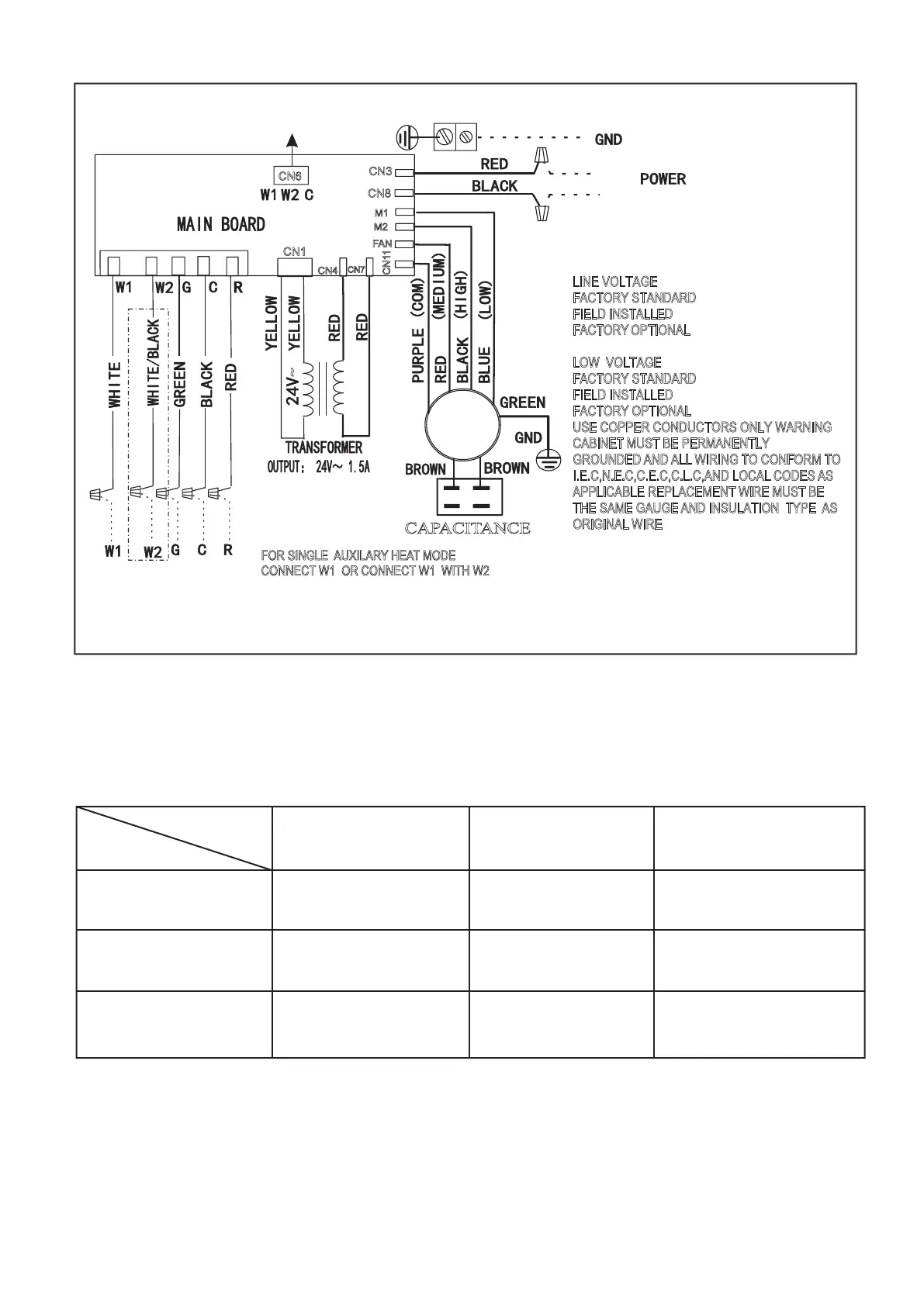
Fig.16 INDOOR UNIT WIRING DIAGRAM FOR PSC MOTOR AC SYSTEMS AND HP SYSTEMS
Terminal
Fan speed
Medium
High
Low
Fan
M1
M2
Red
Blue Black
Black
Blue
Red
Blue
Red
Black
Note: Description of fan speed switch
1.Default as medium speed of factory settings.
2.High speed wiring: Switch to high speed (black wire) and connect with FAN terminal, while medium speed (red wire) connect
with M2 terminal.
3.Low speed wiring: Switch to low speed (blue wire) and connect with FAN terminal, while medium speed (red wire) connect with
M1 terminal.
~
CAPACITANCE
CN7
CN8
CN4
CN1
C
N
1
1
M1
CN3
LINE VOLTAGE
F
ACTORY STANDARD
F
IELD INSTALLED
OPTIONAL
LOW
FACTORY
VOLTAGE
FACTORY STANDARD
FIELD INSTALLED
FACTORY OPTIONAL
USE COPPER CONDUCTORS ONLY WARNING
C
ABINET MUST BE PERMANENTLY
G
ROUNDED AND ALL WIRING TO CONFORM TO
I
.E.C,N.E.C,C.E.C,C.L.C,AND LOCAL CODES AS
APPLICABLE REPLACEMENT WIRE MUST BE
THE SAME GAUGE AND INSULATION TYPE AS
ORIGINAL WIRE
L2
L1
FOR OPT IONAL
ELECTRIC HEAT
CN6
FOR SINGLE HEAT MODE
CONNECT W1 OR CONNECT W1 WITH W2
AUXILARY
M2
TO THERMOSTAT
FAN
MOTOR
FAN
 Loading...