Section 6. Performance and Electrical Data
JMM4A0A18 21SAA
JMM4A0A24 21SAA
JMM4A0B30 21SAA
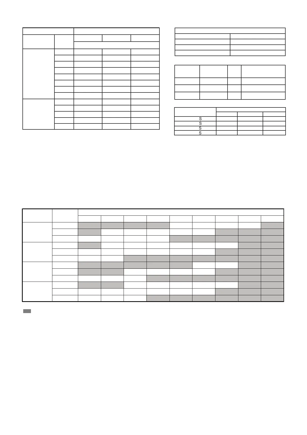
Section 5. - Heater Pressure Drop Table - Use For All TMM4B Wall Mount Air Handler Models
SKC A R FO REBMUN
NUMBER
OF RACKS
NUMBER OF RACKS
W O LFRIA
MODEL
CFM
1 2 3
.G. W SEHCNI - PO R D ERUSSERP RIA
1400
JMM4A0B30 , 36
JMM4A0A18, 24
0.06 0.08 0.08
1300 0.06 0.08 0.08
1200 0.06 0.08 0.08
1100 0.06 0.08 0.08
1000 0.06 0.08 0.08
900 0.04 0.06 0.06
800 0.04 0.06 0.06
700 0.04 0.06 0.06
900 0.04 0.06 0.06
800 0.04 0.06 0.06
700 0.04 0.06
600 0.04 0.06
0.06
0.06
500 0.04 0.06 0.06
SKC A R RET A EH
LEDOM RET A EH N O SKC A R FO .
B A YHTRJ505BRKA*
1
B A YHTRJ508BRKA*
2
B A YHTRJ510BRKA*
3
Accessory Heater Usage
SIZES
USED WITH
kW
INTERNAL CIRCUIT
PROTECTION
5 1 C i u c r i t B reaker
.7 2 5 C i u c r i t B reaker
3
18 6 3 -
18 6 3 -
18 3 - 6 1 0 C i u c r i t B reaker
Minimum CFM
MODEL
1 2 3
450 500 600
450 500 600
70 0 72 5 75 0
JMM4A0B36 31SAA
70 0 72 5 75 0
(WALL-MOUNT AIR HANDLERS ARE SUITABLE
FOR MOBILE HOME APPLICATIONS)
0 0.1 0.2 0.3 0.4 0.5 0.6 0.7 0.8
High 813 775 731 692 653 609 560 501 424
Med 695 656 620 581 540 498 440 380 -
Low 603 562 525 485 443 393 - - -
High 947 895 847 799 753 704 655 592 530
Med
845 801 759 716 675 626 573 510 -
Low
676 640 602 563 523 499 - - -
High 1367 1312 1252 1192 1131 1063 990 908 821
Med 1211 1165 1114 1065 1016 960 899 833 748
Low 992 952 912 873 828 782 728 656 627
High
1397 1345 1290 1263 1196 1116 1051 980 907
Med
1298 1252 1198 1147 1094 1037 976 910 842
Low 1149 1105 1056 1008 960 909 856 791 726
36
EXTERNAL STATIC PRESSURE (in.w.c.)
24
30
MODEL
JMM4A
BLOW ER
SPEEDS
18
--- Shaded boxes represent airflow outside the required 300-450 cfm/ton.
NOTES:
1. Airflow based upon dry coil at 230V with no electric heat and factory---approved filter.
2. Airflow is equivalent for front or bottom return configurations.
The air distribution system has the greatest effect on airflow. The duct system is totally controlled by the contractor. For this reason, the contractor
should use only industry-recognized procedures.
Duct design and construction should be carefully done. System performance can be lowered dramatically through bad planning or workmanship.
Air supply diffusers must be selected and located carefully. They must be sized and positioned to deliver air along the perimeter of the space. If
they are too small for their intended airflow, they become noisy. If they are not located properly, they cause drafts. Air grilles must be properly sized
to carry air back to the blower.If they are too small, they also cause noise.
The installers should balance the air distribution system to ensure proper quiet airflow to all rooms in the home. This ensures a comfortable living
space.
Airflow performance data is based on cooling performance with a coil and no filter in place. Select performance table for appro
priate unit size.
External static applied to unit allows operation within the minimum and maximum limits shown in table below for both cooling an
d electric heat
operation.
PSC-Airflow Performance (Standard CFM)
 Loading...