Routine Maintenance
72 CLCH-SVX009L-EN
Fans
Inspecting and Cleaning Fans
Fan sections of air handlers should be inspected every six
months at a minimum or more frequently if operating
experience dictates. If evidence of microbial growth (mold) is
found, identify and remedy the cause immediately. Refer to
“Troubleshooting,” p. 74 for possible causes and solutions. To
clean the fan section:
1. Disconnect all electrical power to the unit.
2. Wearing the appropriate personal protective equipment,
remove any contamination.
3. Vacuum the section with a vacuum device that uses high-
efficiency particulate arrestance (HEPA) filters with a
minimum efficiency of 99.97 percent at 0.3 micron particle
size.
4. Thoroughly clean any contaminated area(s) with a mild
bleach and water solution or an EPA-approved sanitizer
specifically designed for HVAC use.
5. Immediately rinse the affected surfaces thoroughly with
fresh water and a fresh sponge to prevent potential
corrosion of metal surfaces.
6. Allow the unit to dry completely before putting it back into
service.
7. Be careful any contaminated material does not contact
other areas of the unit or building. Properly dispose of all
contaminated materials and cleaning solution.
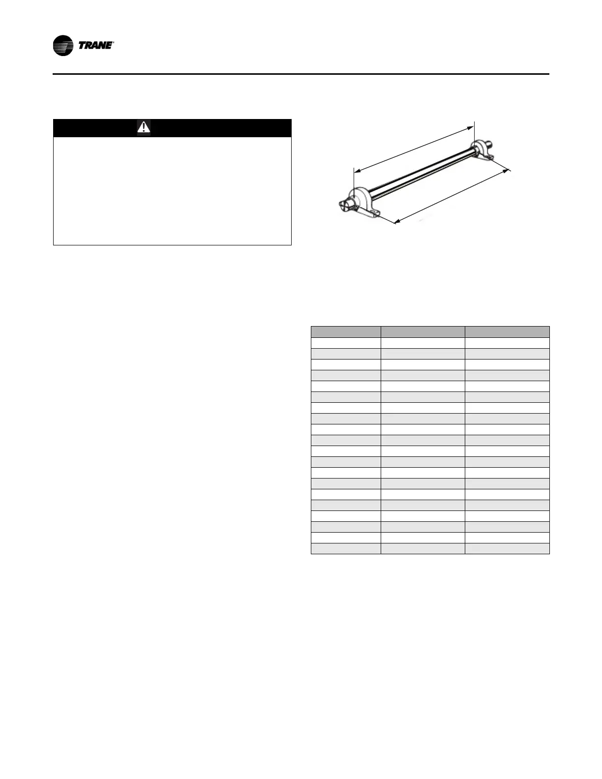
Bearing Set Screw Alignment
Align bearing set screws for belt-drive fans as illustrated in
Figure 75. See Table 17, p. 64 for set screw torque
measurements.
Torque Requirements
Refer to Table 19 for minimum torque of motor mounting and
bearings bolts. Refer to Table 17, p. 64 for minimum set screw
torque.
WARNING
Rotating Components!
Failure to secure rotor or disconnect power before
servicing could result in rotating components cutting
and slashing technician which could result in death or
serious injury. The following procedure involves
working with rotating components. Disconnect all
electric power, including remote disconnects before
servicing. Follow proper lockout/ tagout procedures to
ensure the power can not be inadvertently energized.
Secure rotor to ensure rotor cannot freewheel.
Figure 75. Bearing set screw alignment
Table 19. Minimum hex head bolt torque in lb.-ft.
(Grade 5 bolts)
Size (inches) Thread Designation Minimum Torque
1/4-20 UNC 6
1/4-28 UNF 7
65/16-18 UNC 14
5/16-24 UNF 16
3/8-16 UNC 24
3/8-24 UNF 28
7/16-14 UNC 42
7/16-20 UNF 45
1/2-13 UNC 69
1/2-20 UNF 83
9/16-12 UNC 99
9/16-18 UNF 118
5/8-11 UNC 150
5/8-18 UNF 176
3/4-10 UNC 254
3/4-16 UNF 301
7/8-9 UNC 358
7/8-14 UNF 422
1-8 UNC 500
1-14 UNF 602
Note: Soft metric conversions are not acceptable for screw and hex sizes.
Align set screws
Align set screws



 To Next Page