26
RT-SVX075C-EN
Clearances
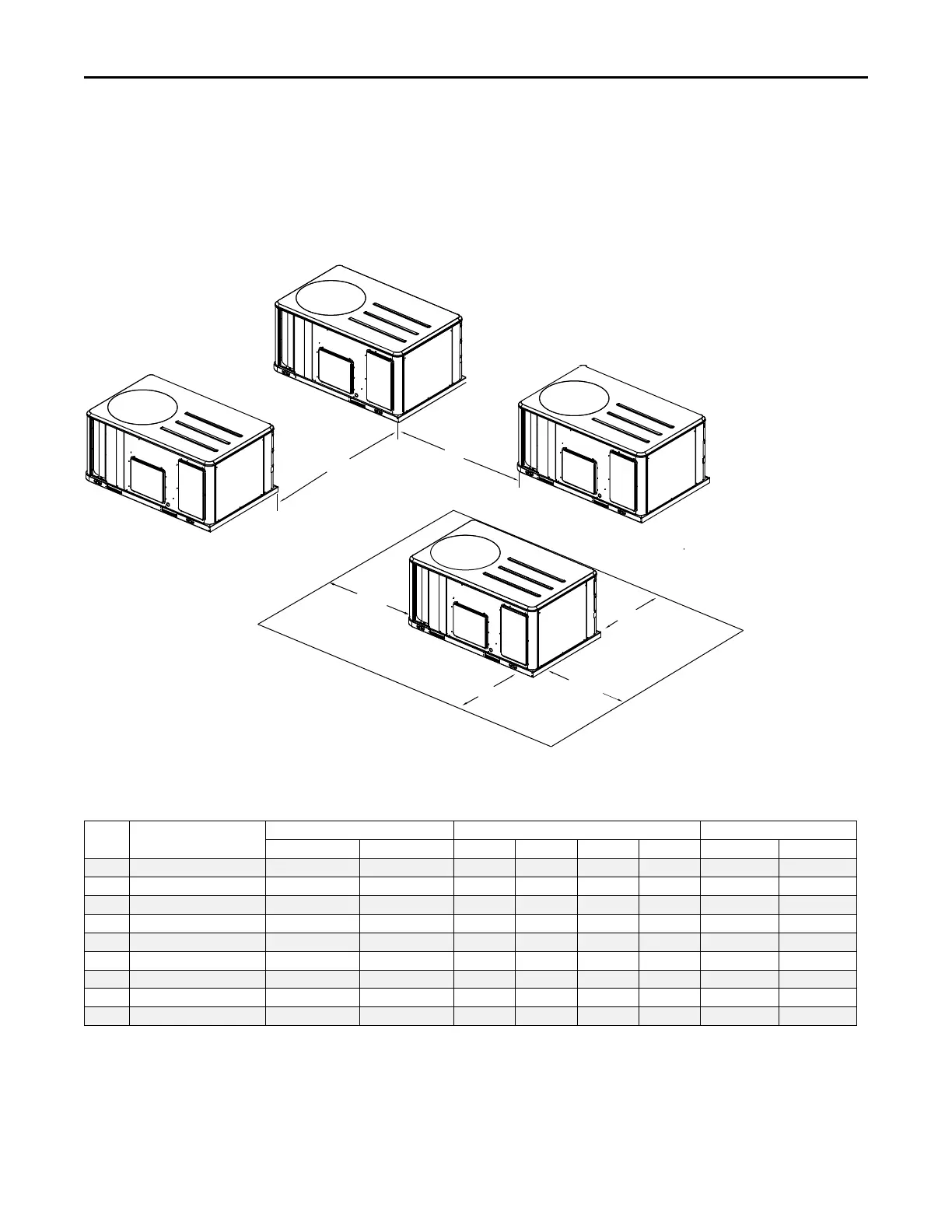
Figure 25, p. 26 illustrates the minimum operating and
service clearances for either a single or multiple unit
installation. These clearances are the minimum distances
necessary to assure adequate serviceability, cataloged unit
capacity, and peak operating efficiency. Providing less than
the recommended clearances may result in condenser coil
starvation, “short-circuiting” of exhaust and economizer
airflows, or recirculation of hot condenser air.
Figure 25. Typical installation clearances for single and multiple unit applications
Side by Side
Note 1
End to End
Note 1, 2
7’0”
2134 MM
6’0”
1829 MM
3’0”
914 MM
Single Unit
3’0”
914 MM
3’0”
914 MM
4’0”
1219 MM
Notes:
1. When equipped with economizer
or barometric relief damper, clearance
distance is to be measured from
protruding hood instead of base.
2. Clearance is the same if any unit
is rotated 180 degrees.
4’0”
1219 MM
for D cabinet
5’0”
1525 MM
for D cabinet
5’8” for D cabinet
1727 MM
Weights
Table 1. Model weights, corner weights (lbs) and center of gravity dimensions (in.)
Tons Unit Model No.
Model Weights
(a)
Corner Weights
(b)
Center of Gravity (in.)
Shipping
Net A B C D
Length
Width
6 YHJ072 1107 1009 331 309 178 191 43 19
7.5 YHJ090 1111 1013 333 310 178 191 43 19
8 YHJ102 1127 1029 338 315 181 194 43 19
10 YHJ120 1137 1039 341 318 183 196 43 19
12.5 YHJ150 1512 1318 385 389 273 270 50 26
15 YHJ180 2220 2000 671 492 354 483 52 36
17.5 YHJ210 2250 2030 672 509 366 484 53 36
20 YHJ240 2320 2100 754 516 337 493 50 34
25 YHJ300 2370 2150 746 529 363 512 51 35
(a)
Weights are approximate. Weights do not include additional factory or field installed options/accessories. For option/accessory additional weights to be added to unit weight,
reference the following table.
(b)
Corner weights are given for information only.
Dimensions and Weights

 Loading...