RT-SVX075C-EN
35
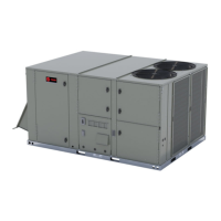
Figure 45. Supply and return opening
Insulation side
down
Supply duct cover
Insulation side up
Return duct
cover
6. After completing installation of the duct covers for
horizontal discharge, proceed to TCO-1 instructions
(two-stage gas only).
DAS Horizontal Conversions
(Select Modulating Gas Heat
Units)
For units with model number digit 10 = B, DAS system
conversion may be required:
• 6 to 12.5 ton units (with model number digit 10 = B):
conversion required to the DAS pickup tubes for
horizontal duct configurations.
• 15 to 25 ton units (with model number digit 10 = B): no
conversion required. The factory-installed DAS system
is applicable to both downflow and horizontal.
Conversion to Horizontal — Models
YHJ072***BH, YHJ(090,102,120,150)***B
(H,L)
The figures shown below are representative. The heat
exchanger size and discharge air tube geometry may vary
with unit configuration. Any variations do not affect the
conversion process.
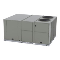
Figure 46. DAS tubing factory installation for
downflow
Vertical slide bracket
Horizontal conversion
elbow - mounted to back
of bracket
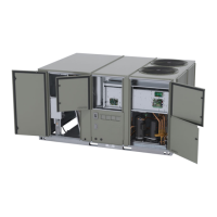
Figure 47. DAS tubing detail view (downflow)
Vertical slide bracket
covers holes in tubing
1. Reposition vertical slide bracket.
a. Remove bracket screw.
b. Slide the bracket down to expose the holes in the
vertical tube. See Figure 48, p. 35, Figure 49, p.
36, and Figure 50, p. 36.
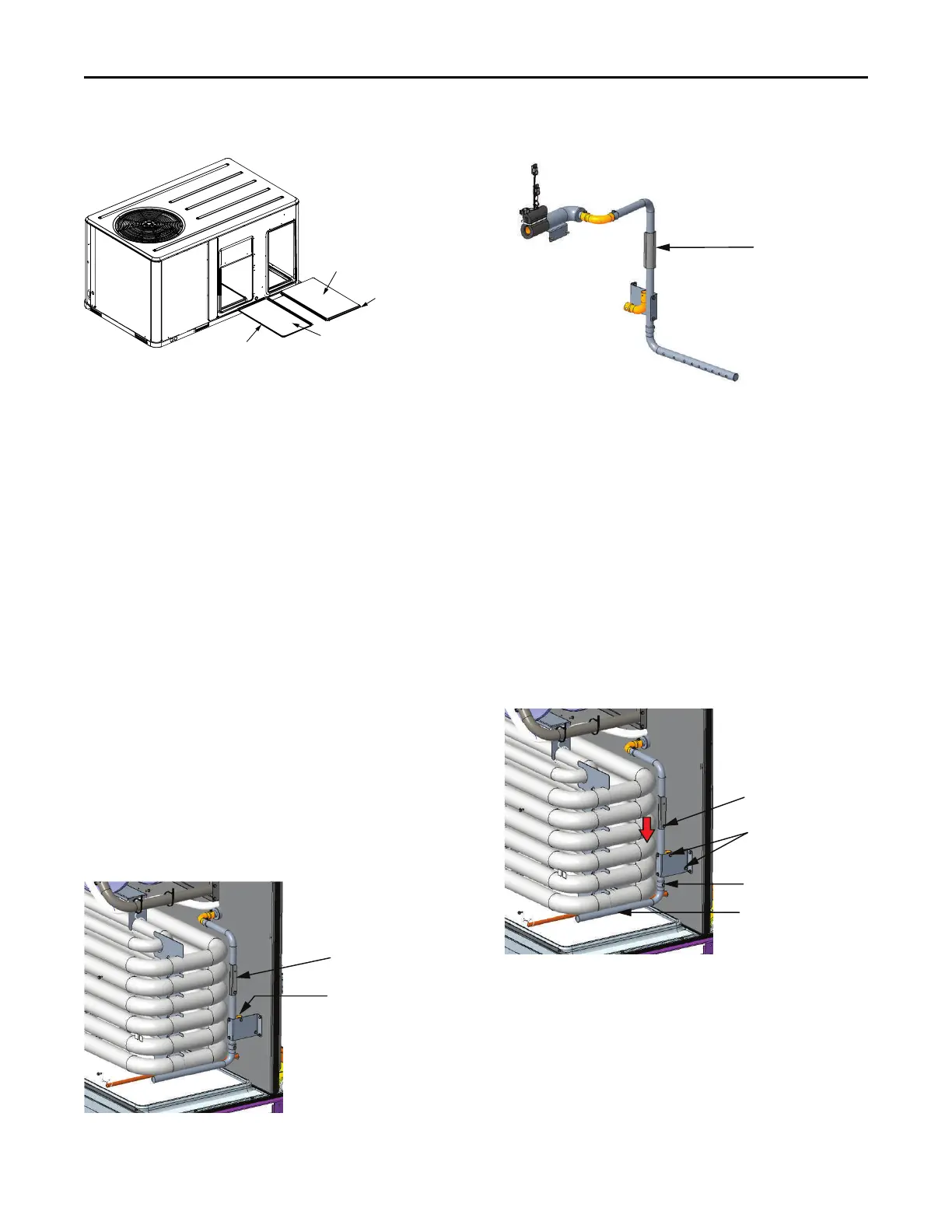
2. Reattach bracket screw to secure vertical slide bracket
in new position.
3. Remove elbow from support bracket.
4. Remove pickup tube from vertical tube.
5. Install 90 degree elbow as shown in Figure 49, p. 36.
6. Reposition pickup tube as shown in Figure 49, p. 36.
Important: To prevent stripping, do not over-tighten the
attachment screws.
Figure 48. DAS tubing conversion components
Vertical slide bracket
attachment screw
Elbow attachment
screws
Pickup sensing tube
attachment screws
Pickup sensing tube
Installation

 Loading...