Installation
36 RT-SVX46G-EN
The transformer is located in the control panel. The circuit
breaker is located on the left side of the transformer and
can be reset by pressing in on the black reset button.
Controls using DC Analog Input/Outputs
(Standard Low Voltage Multi-Conductor
Wire)
Before installing any connecting wiring between the unit
and components utilizing a DC analog input\output signal,
refer to the Dimensions and Weights chapter for the
electrical access locations provided on the unit.
• Table 5, p. 36 lists the conductor siz
ing
guidelines that
must be followed when interconnecting the DC binary
output devices and the system components utilizing a
DC analog input/output signal to the unit.
Note: Re
sistance in excess of 2.5 ohms per conductor can
caus
e deviations in the accuracy of the controls.
Note: Ensure
that the wiring be
tween controls and the
unit’s termination point does not exceed two and a
half (2.5) ohms/conductor for the length of the run.
• Do not run the electrical wires transporting DC signals
in
or around conduit housing high voltage wires.
• Route low voltage wiring per illustrations on page 37.
DC Conductors
WARNING
Hazardous Voltage!
Failure to disconnect power before servicing could
result in death or serious injury. Disconnect all electric
power, including remote disconnects before servicing.
Follow proper lockout/tagout procedures to ensure the
power can not be inadvertently energized.
Table 5. Zone sensor module wiring
Distance from Unit to Control Recommended Wire Size
0 - 150 feet 22 gauge
0 - 45.7 m 0.33 mm
2
151 - 240 feet 20 gauge
46 - 73.1 m 0.50 mm
2
241 -385 feet 18 gauge
73.5 - 117.3 m 0.75 mm
2
386 - 610 feet 16 gauge
117.7 - 185.9 m 1.3 mm
2
611 - 970 feet 14 gauge
186.2 - 295.7 m 2.0 mm
2
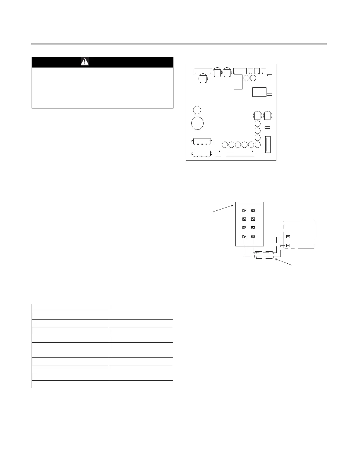
Figure 63. ReliaTel™ options module
Figure 64. ReliaTel™ relative humidity sensor
(enhanced dehumidification operation)
J8
TP1
DA COOL
FAN S PD
TP2
DA HEAT
TP3
EXH
FAN
SPC PRESS
DB
SPC PRESS
J4
J9 J10
J11
J12
J3
TP4
TP5
DEHUMID
TB1
TB2
J6
J7J5
J1
J2
Low Voltage
Terminal Block
NLTB
NLTB
Located on Front
of Rooftop Unit
Control Box
Relative Humidity
Sensor
(Field Supplied)
Field Supplied
Cable
NLTB
12
13
15
17
19
14
16
18
R.H.+
R.H.-