Pre-Start
42 RT-SVX46G-EN
Test Modes
There are three methods in which the “Test” mode can be
cycled at LTB-Test 1 and LTB-Test 2.
1. Step Test Mode - This method initiates the different
com
po
nents of the unit, one at a time, by temporarily
shorting across the two test terminals for two to three
seconds. For the initial startup of the unit, this method
allows the technician to cycle a component “On” and
have up to one hour to complete the check.
2. Resistance Test Mode - This method can be used for
startu
p prov
iding a decade box for variable resistance
outputs is available. This method initiates the different
components of the unit, one at a time, when a specific
resistance value is placed across the two test
terminals. The unit will remain in the specific test mode
for approximately one hour even though the
resistance is left on the test terminals.
3. Auto Test Mode - This method is not recommended
for
startup du
e to the short timing between individual
component steps. This method initiates the different
components of the unit, one at a time, when a jumper
is installed across the test terminals. The unit will start
the first test step and change to the next step every 30
seconds.
At the end of the test mode, con
trol of the unit will
automatically revert to the applied “System” control
method.
For unit test steps, test modes, and step resistan
ce valu
es
to cycle the various components, refer to Table 9, p. 42.
ReliaTel™ Controls
Upon power initialization, the Gas Ignition Module (IGN)
performs self-diagnostic checks to insure that all internal
controls are functional. It also checks the configuration
parameters against the components connected to the
system. The System LED located on the IGN module is
turned “On” within one second of power-up if internal
operation is okay.
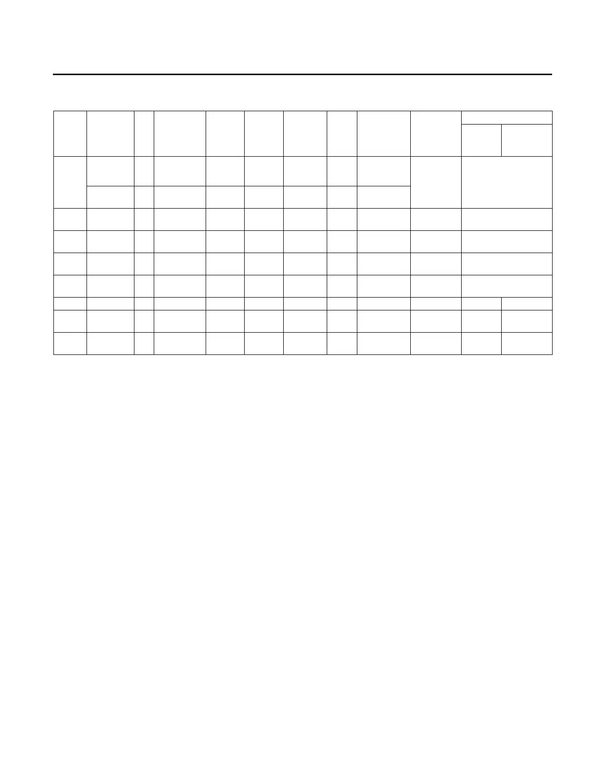
Table 9. Service test guide for component operation
Test
Step
Mode Fan Econ
(a)
Comp 1 Comp 2 Heat 1 Heat 2
Modulating
Heat
Resistance
Supply Fan Output
(b)
Cool and
Staged
Heat
Modulating
Heat
1
Fan On
Minimum
Position
Setpoint
0%
Off Off Off Off 0%
2.2K
Ω 50%
Minimum
Ventilation
On Selectable Off Off Off Off 0%
2
Economizer
Test Open
On Open Off Off Off Off 0% 3.3K
Ω 50%
(c)
3
Cool
Stage 1
On
Minimum
Position
On
(d)
Off Off Off 0% 4.7KΩ 82%
4
(e)
Cool
Stage 2
On
Minimum
Position
On
(d)
On
(d)
Off Off 0% 6.8KΩ 100%
5
(e)
Cool
Stage 3
On
Minimum
Position
On
(d)
On
(d)
Off Off 0% 8.2KΩ 100%
6
(e)
Reheat On Minimum On On Off Off 0% 33KΩ 100%
(f)
—
7
(e) (g)
Heat
Stage 1
On Minimum Off Off On/50%
(h)
Off 50% 10KΩ 100% 50%
(h)
8
(e)
Heat
Stage 2
On Minimum Off Off
On/
100%
(h)
On 100% 15KΩ 100% 100%
(h)
(a) The exhaust fan will turn on anytime the economizer damper position is equal to or greater than the exhaust fan setpoint.
(b) The supply fan output is in reference to the user selected maximum unit fan speed.
(c) Regardless of the economizer mode configuration, the unit will run the supply fan at the minimum speed during the economizer step of the service test.
(d) The condenser fans will operate any time a compressor is ‘On’ prov
iding the outdoor air temperatures are within the operating values.
(e) Steps for optional accessories and non-appli
cable modes in unit will be skipped.
(f) Units with enhanced dehumidification only will no
t perform this step during service test.
(g) For ultra Low NOX gas furnace units, the vestibule temperature limit switch must also be in closed state in order for the gas valve an
d the premix blower
to be energized for Heat Stage 1.
(h) Supply fan output for modulating gas heat will be a percentage of the user selected maximum supply fan speed. Values shown represent SZVAV/MZVAV.