Maintenance
RT-SVX46G-EN 49
2. Protect all electrical devices such as motors and
controllers from any over spray.
3. Straighten any bent coil fins with a fin comb.
4. Mix the detergent with wa
te
r according to the
manufacturer’s instructions. If desired, heat the
solution BUT DO NOT EXCEED 150ºF maximum to
improve its cleansing capability.
5. Pour the cleaning solution into the sprayer. If a high-
pr
essure
sprayer is used:
a. do not allow sprayer pressure to exceed 600 psi.
b. the minimum nozzle spray angle is 15 degrees.
c. maintain a minimum clearance of 6-inch between
th
e sprayer
nozzle and the coil.
d. spray the solution perpendicular (at 90 degrees) to
the coil face.
6. Spr
ay the leaving-airflow side of the coil fi
rst; then
spray the opposite side of the coil. Allow the cleaning
solution to stand on the coil for five minutes.
7. Rinse both sides of the coil
with cool, clean water.
8. I
nspect both sides of the coil; if it still appears to be
dirty, repeat Step 6 and Step 7.
9.
Reinstall all of the components and panels removed in
Step 1 and any protective covers installed in Step 2.
Note: For u
nits equipped with hail guards follow
reinstallation procedure listed below.
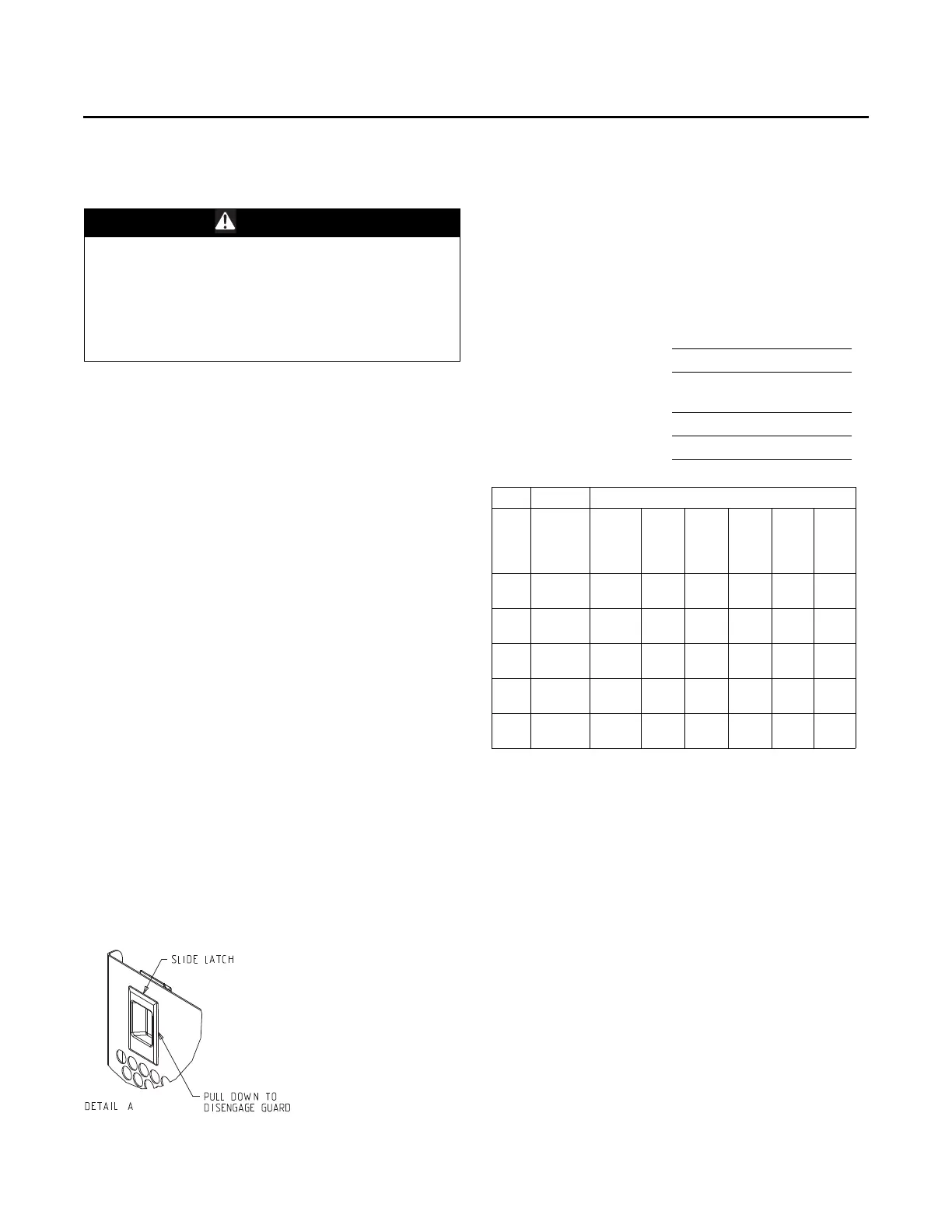
Hail Guard Reinstallation
10. To reinstall the hail guard, locate the bottom of the hail
guard in the lower bracket and secure it to the upper
unit bracket with the attached fasteners.
Note: Secure h
ail guard latches.
11. Restore the unit to its operational status and check
system
operation.
Annual Maintenance
• Clean and repaint any corroded surface.
Final Process
For future reference, you may find it helpful to record the
unit data requested in the blanks provided.
Note: Check and record the data requested above each
month during the cooling season with the unit
running.
WARNING
Hazardous Pressures!
Failure to follow safety precautions below could result
in coil bursting, which could result in death or serious
injury. Coils contain refrigerant under pressure. When
cleaning coils, maintain coil cleaning solution
temperature under 150°F to avoid excessive pressure
in the coil.
Figure 72. Hail guard
Complete Model Number:
Unit Serial Number:
Wiring Diagram Numbers
(from un
it control panel):
Connections:
Schematics:
Table 10. Sample maintenance log
Refrigerant Circuit #1
Date
Current
Ambient
Temp.
F/C
Compr.
Oil
Level
Suct.
Press.
Psig/
kPa
Disch.
Press.
Psig/
kPa
Liquid
Press.
Psig/
kPa
Super
-heat
F/C
Sub-
cool.
F/C
- ok
- low
- ok
- low
- ok
- low
- ok\
- low
- ok
- low