54 RLC-SVX07A-EN
Installation - Remote Condenser
Discharge (Hot Gas) Line Sizing
The discharge lines should pitch downward, in the direction of the hot gas
flow, at the rate of 1/2 inch per each 10 feet of horizontal run.
Discharge line size is based on the velocity needed to obtain sufficient oil
return. Basic discharge line sizing is shown in Tables 11and 12, depending on
the unit configuration.
NOTE: The proper column for leaving evaporator water temperature must
be used to avoid catastrophic damage to the unit. Columns for 0 F to 19 F and
20 F to 39 F can only be used on units designed for low temperature applica-
tions. Refer to the design conditions of the unit to determine the correct
column that must be used.
NOTE: The discharge line should drop well below the compressor discharge
outlet before beginning its vertical rise. This prevents possible refrigerant
drainage back to the compressor and oil separator during the unit STOP cycle.
Refer to Figures 23, 24 and 25 for details.
Refrigerant Sensors
If a Trane RTCA condenser is used with the RTUA unit, no sensors need to be
field installed.
If a non-RTCA condenser is used, an outdoor ambient temperature sensor
and a saturated condenser temperature sensor must be installed for the
RTUA to control properly. The outdoor ambient temperature sensor must be
installed in a location that accurately represents the outdoor ambient temper-
ature which the condenser will encounter. It must not be exposed to direct
sunlight or precipitation which could artificially alter the actual outdoor
ambient temperature. Also, it must not be exposed to the recirculating air
from the discharge of the condenser.
The saturated condensing temperature sensors must be installed on the
refrigerant piping which leaves the condenser and enters the subcooler on
both circuits. Strap the sensor into place, similar to the method used with
most thermal expansion valve sensing bulbs. This sensor can be mounted
externally if it is sufficiently insulated. The insulation covering the sensor
must be capable of withstanding the higher temperatures without degra-
dation. Failure to properly mount and insulate the saturated condensing refrig-
erant temperature sensor could cause poor control and/or possible
compressor damage.
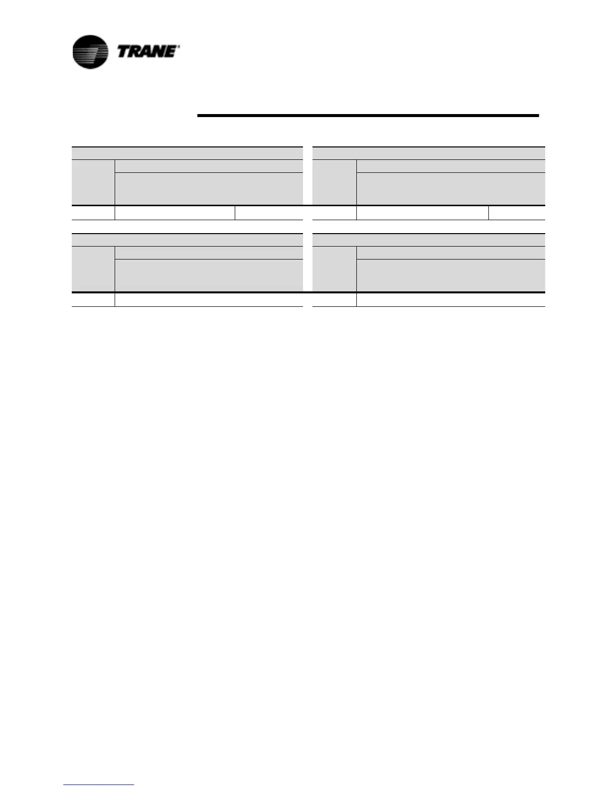
Table 13 Upflow Discharge Line Sizes (O.D.)
35 Ton Circuit 40 Ton Circuit
To t a l
Equiv.
Length
(ft.)
Leaving Evaporator Water Temperature (F) To t a l
Equiv.
Length
(ft.)
Leaving Evaporator Water Temperature (F)
40 - 60 F 20 - 39 F 0 - 19 F 40 - 60 F 20 - 39 F 0 - 19 F
0 - 300 ft. 2 1/8 1 5/8 1 5/8 0 - 300 ft. 2 1/8 1 5/8 1 5/8
50 Ton Circuit 60 Ton Circuit
To t a l
Equiv.
Length
(ft.)
Leaving Evaporator Water Temperature (F) To t a l
Equiv.
Length
(ft.)
Leaving Evaporator Water Temperature (F)
40 - 60 F 20 - 39 F 0 - 19 F 40 - 60 F 20 - 39 F 0 - 19 F
0 - 300 ft. 2 1/8 2 1/8 1 5/8 0 - 300 ft. 2 1/8 2 1/8 1 5/8
 Loading...


