Replacement Procedure
8 PART-SVN251A-EN
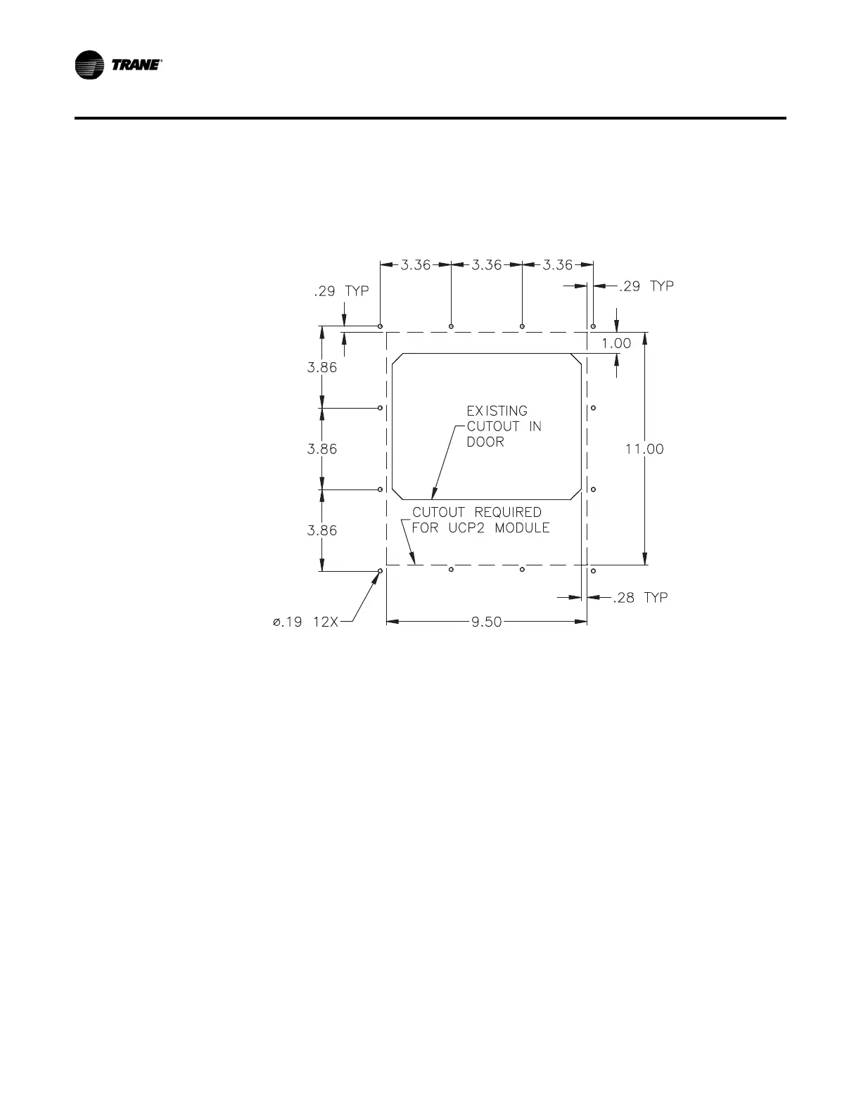
f. Trace square on door as shown in Figure 1, p. 7.
g. Cut along the traced lines.
h. Deburr the edges of the new hole.
Figure 1. Existing cutout and modifications required
5. Install the CLD2 into the control panel door.
a. Using the new CLD as your template. Hold up the new CLD to the hole and make marks
where holes
should be drilled.
b. Drill holes.
c. Starting at the top, attach brackets from the outside of the door in such a way that the door
panel is
sandwiched between the CLD on the inside and mounting brackets on the outside
of the door panel as shown in Figure 2. The screw head should be flush with the bracket.
d. Tighten the nuts so that the gasket on the CLD is properly compressed.
e. Remove the tape backing from the plastic bezel and apply it to the outside of the door
opening so
it covers the mounting brackets.