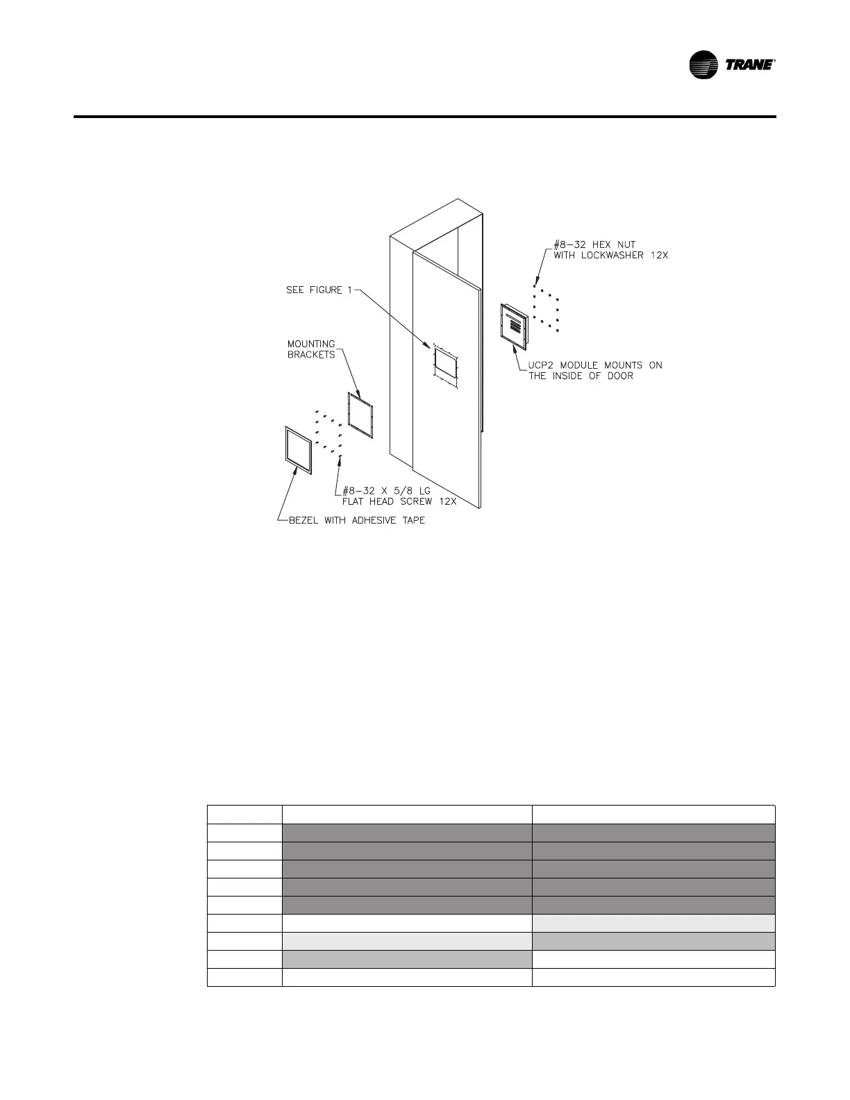
Figure 2. New CLD assembly
Replacement Procedure
PART-SVN251A-EN 9
6. Replace the 1U1 module.
a. If required, mark the wires connected to TB1, TB2, TB3, TB4, and TB5.
b. Remove all wires and connectors from the 1U1 module.
c. Loosen but
do not remove the two lower 1U1 mounting screws.
d. Remove the two upper 1U1 mounting screws. If star washers exist on any of the screws, be
careful not
to lose them.
e. Remove the 1U1 from the control panel.
f. Install the new 1U1 into the control panel reusing the same screws.
g. Replace the two upper 1U1 mounting screws.
h. Tighten the two lower 1U1 mounting screws.
i. Re-connect wiring to the 1U1. There are differences between TB4 on the old and new 1U1.
Refer
to Table 7 when
reconnecting wiring to that terminal block.
Table 7. Old-to-new wiring terminal positions on CPM
Terminal 130-400T RTAA 1U1 New RTAA 1U1
TB4-1 ALARM (COMMON) ALARM (COMMON)
TB4-2 ALARM (NORMALLY OPEN) ALARM (NORMALLY OPEN)
TB4-3 ALARM (NORMALLY CLOSED) ALARM (NORMALLY CLOSED)
TB4-4 COMPRESSOR RUNNING (COMMON) COMPRESSOR RUNNING (COMMON)
TB4-5 COMPRESSOR RUNNING (NORMALLY OPEN) COMPRESSOR RUNNING (NORMALLY OPEN)
TB4-6
COMPRESSOR RUNNING (NORMALLY CLOSED) MAXIMUM CAPACITY (COMMON)
TB4-7 MAXIMUM CAPACITY (NORMALLY COMMON) MAXIMUM CAPACITY (NORMALLY OPEN)
TB4-8 MAXIMUM CAPACITY (NORMALLY OPEN) EVAPORATOR PUMP (COMMON)
TB4-9 EVAPORATOR PUMP (NORMALLY OPEN)