Table 3 Isolator Selection
Unit Model
Neoprene Isolator
Part Number
Quantity Maximum load weight per isolator (kg)
X10140305630 6 1361
X10140305640 8 1814
X10140305640 8 1814
X10140305630 8 1361
X10140305630 8 1361
X10140305630 14 1361
X10140305630 14 1361
X10140305640 8 1814
X10140305630 8 1361
X10140305630 16 1361
X10140305630 16 1361
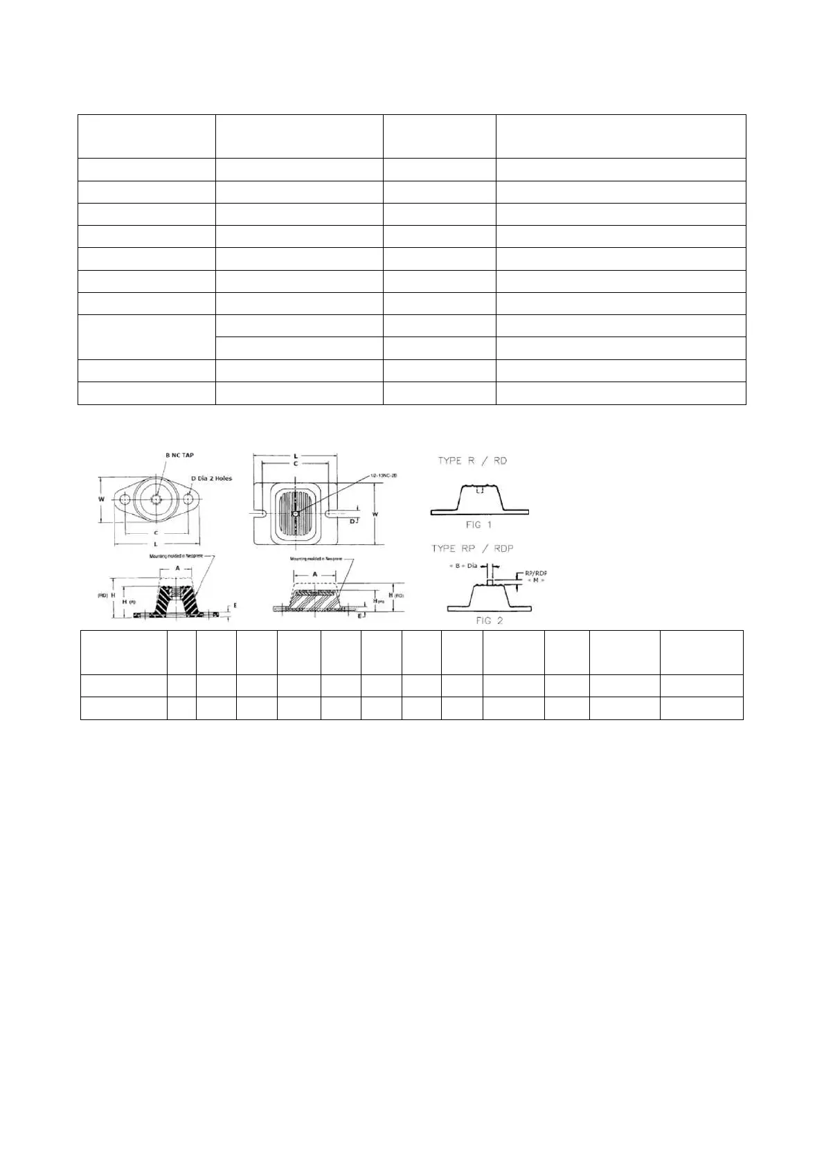
TYPE R1,R2,RJ-RD1 ,RD2,R03 TYPE R4-RD4
A (mm)
B
C (mm)
D (mm)
E
H
L (mm)
M (mm) W (mm)
T
yp
e
Colour
76.2
14.2
RDP4-WR Green-yellow
76.2
14.2
RDP4-WR Dark-grey
Figure 6 Neoprene Isolator
Cover Plate for combined unit Installation
1. Keep master and slave units level and aligned.
2. Cover plate 1 (10 kg) and plate 2 (21kg) are installed on site.
3. As detailed Detail I of Figure 7, first unscrew the total 32 M6 tapping screws, and install back after the cover
plate placed in right position.
Note: Cover Plate applicable to RTXC310,330,360,400,440XE.