CTV-SVX06J-EN
19
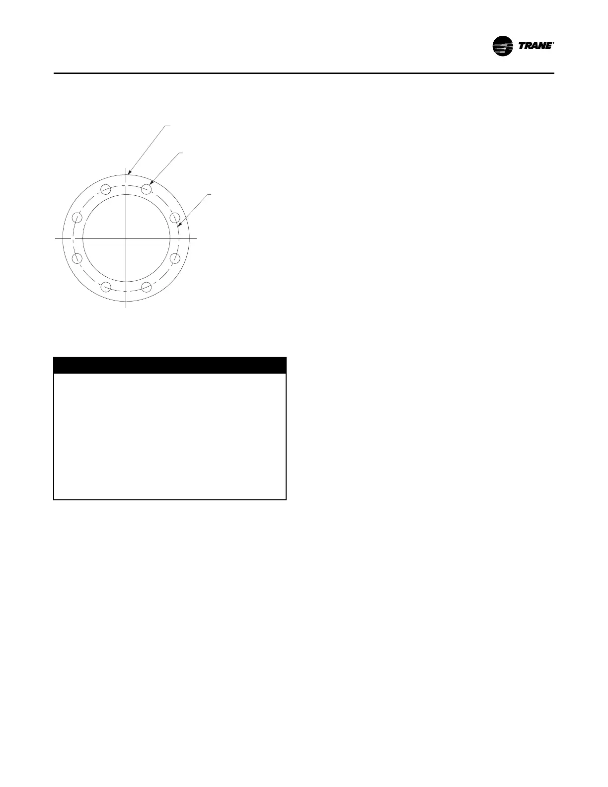
Figure 18. Four-inch (101.6 mm) RuptureGuard flange, in. (mm)
9.00 (228.6) OD
6.19 (157.2) ID
0.88 (22.4) Thick
Ø.75 (Ø19.1), 8X
Equally Spaced
Ø7.50
(Ø190.5)
Connection to External Vent
Line and Drip Leg
NNOOTTIICCEE
EEqquuiippmmeenntt DDaammaaggee!!
FFaaiilluurree ttoo ffoollllooww iinnssttrruuccttiioonnss bbeellooww ccoouulldd rreessuulltt iinn
eeqquuiippmmeenntt ddaammaaggee..
AAllll vveenntt lliinneess mmuusstt bbee eeqquuiippppeedd wwiitthh aa ddrriipp lleegg ooff
ssuuffffiicciieenntt vvoolluummee ttoo hhoolldd tthhee eexxppeecctteedd
aaccccuummuullaattiioonn ooff wwaatteerr aanndd//oorr rreeffrriiggeerraanntt.. TThhee ddrriipp
lleegg mmuusstt bbee ddrraaiinneedd ppeerriiooddiiccaallllyy ttoo aassssuurree tthhaatt iitt
ddooeess nnoott oovveerrffllooww aanndd aallllooww fflluuiidd ttoo ffllooww iinnttoo tthhee
hhoorriizzoonnttaall ppoorrttiioonn ooff tthhee vveenntt lliinnee.. TTrraannee aassssuummeess
nnoo rreessppoonnssiibbiilliittyy ffoorr eeqquuiippmmeenntt ddaammaaggee ccaauusseedd bbyy
iinnssuuffffiicciieenntt ddrraaiinnaaggee ooff ddrriipp lleegg..
With RuptureGuard™ installed horizontally, the drain
plug downstream of the valve relief plug and nearest to
the bottom of the valve body should be piped to the
drip leg in the vent line (refer to the following figure).
This will allow the removal of any condensate formed
within the valve body.
Provisions, such as installing a set of flanges (refer to
the following figure) or other disconnect means, must
be made in the discharge vent piping. This will allow
the piping downstream of the valve to be easily
removed for an annual inspection, to replace the metal
RuptureGuard™ disk, or for any other servicing need.
1. Connect the discharge of the valve assembly to the
vent line connected to the outdoors.
NNoottee:: The rated flow capacity of the
RuptureGuard
™
disk/valve assembly is based
on having straight pipe extending past the
spring mechanism downstream of the valve.
Make sure there are no crosses (a derate on
the rated flow capacity for this configuration
is published in Engineering Bulletin:
RuptureGuard Selection Guide [E/CTV-EB-
10]), elbows, tees, or any other obstructions
within the first 9 in. (22.86 cm) of valve
discharge. Refer to the chiller installation
manual, ASHRAE Standard 15, national, state,
and local codes for additional requirements
on piping rupture disk and relief valve vent
lines.
2. With the RuptureGuard™ installed horizontally,
remove the drain plug downstream of the valve
relief plug and nearest to the bottom of the valve
body and pipe a drain line to the drip leg in the vent
line.
IImmppoorrttaanntt:: The purge exhaust line MUST be
connected to the downstream side
piping to vent purge exhaust out the
vent line to the outdoors; it may need to
be extended to the drip leg (refer to the
following figure). Field-acquired tubing
may be required to extend to the field-
supplied vent piping, depending on
distance. Do NOT create a U-trap in the
purge exhaust line; this line MUST be
sloped from purge (highest point
toward field-supplied piping, lower
point toward connection) to allow
proper draining of any condensation.
IInnssttaallllaattiioonn