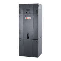
9
Coil Support
Channel
STEP 6 - Slide Coil assembly out of unit using built-
in coil support channels and set aside.
STEP 7 - Use a 5/16 Allen wrench on the locking
mechanism on each side of the bottom half of the
cabinet to loosen the locking mechanism. The locks
loosen by turning counter-clockwise approximately
3/4 of a turn.
STEP 5 - Disconnect wires to the EEV motor and
sensors inside the coil assembly. Cut the wire ties
on those wire harnesses.
Note: If cut, wire ties that held the sensor must
be replaced after the coil is placed back into the
cabinet.

 Loading...


