3270 3332 C 6
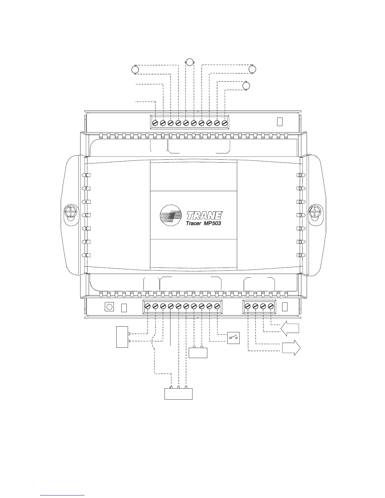
Figure 7. Input/output terminal wiring diagram for the Tracer MP503
1 GND
UNIVERSAL INPUTS
LED
COMM5
LED
PIN
SERVICE
BINARY OUTPUTS
GND
24V
AC POWER
STATUS
LED
DC OUT
24V 24V
COMM5
BAAB
2 GND 3 GND 4 GND
1 GND 2 GND 3 GND 4 GND
Typical relay On/Off
Not
used
In
LonTalk
®
communication
link
Out
Typical relay On/Off
Typical relay On/Off
Typical relay On/Off
Ty p i c al
thermistor
sensor
Ty pic al 2 -wi re
4–20 mA
sensor
Ty p i c a l 3 - w i r e
0–10 Vdc sensor
–
+
–
+
Ty p i c a l
binary
switching
device
GND
24V
GND
The following are trademarks or registered trademarks of American Standard Inc.: Rover, Tracer, Tracer Summit, Tracker.
The following are trademarks or registered trademarks of their respective companies or organizations: LonTalk from Echelon;
National Electrical Code from National Fire Protection Association.
™
®
™
®

 Loading...


