3270 3332 C 4
AC-power wiring
See Figure 5 or Figure 6 for the location of the AC-
power connections.
IMPORTANT
Make sure that the 24 Vac power supplies are
consistently grounded. Do not share 24 Vac between
I/O modules.
The recommended wire for AC-power is 16 AWG
copper wire. All wiring must comply with National
Electrical Code
®
and local codes.
Use a UL-listed Class 2 power transformer
supplying a nominal 24 Vac (20–30 Vac). The
transformer must be sized to provide adequate
power to the Tracer MP503 (10 VA) and outputs (a
maximum of 12 VA per binary output).
WARNING
Hazardous voltage!
Disconnect all electric power, including remote
disconnects before servicing. Follow proper lockout/
tagout procedures to ensure the power cannot be
inadvertently energized. Failure to disconnect power
before servicing could result in death or serious
injury.
CAUTION
Personal injury and equipment damage!
After installation, make sure that the 24 Vac
transformer is grounded through the board. Failure
to do so may result in personal injury and/or damage
to equipment.
CAUTION
Equipment damage!
Complete input/output wiring before applying
power to the controller. Failure to do so may cause
damage to the controller or power transformer due
to inadvertent connections to power circuits.
CAUTION
Equipment damage!
Do not share 24 Vac between controllers. Sharing
24 Vac power may cause controller damage.
Wiring AC-power to the frame-mount I/O
module
Please read the preceding warning and cautions. To
connect AC-power to the frame-mount I/O module:
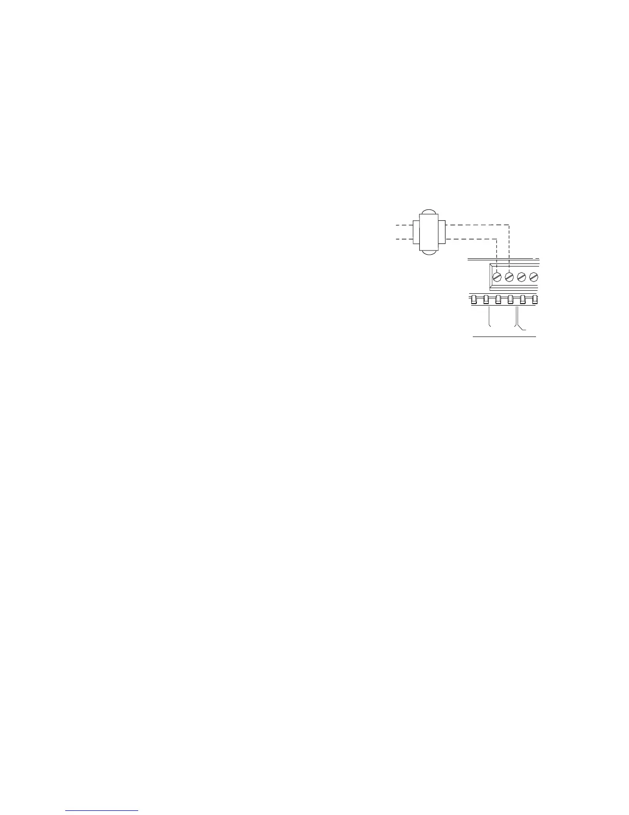
1. Connect one secondary wire from the 24 Vac
transformer to the GND terminal shown in
Figure 5.
2. Connect the other secondary wire to the 24V
terminal.
Figure 5. AC-power wiring for frame-mount
Wiring AC-power to the metal-enclosure
I/O module
Please read the preceding warnings and cautions. To
connect AC-power wiring to the enclosure:
1. Remove the cover of the enclosure.
2. Remove the knockout for the 0.5 in. (13 mm)
conduit from the enclosure and attach the
conduit.
3. Feed the power wire into the enclosure.
4. When mounting on dry wall or other non-
conductive surface, connect an earth ground to
the earth-ground stud on the enclosure (Figure
6).
5. Connect one secondary wire from the 24 Vac
transformer to the GND terminal.
6. Connect the other secondary wire to the 24V
terminal.
7. Replace the cover of the enclosure.
BIN
1
GND
24V
AC POWER
GND
24 Vac
transformer
24V
GND

 Loading...


