12 18-CD19D5-10
Installer’s Guide
VENT FITTING MATERIAL – PLASTIC
Gas and liquid tight single wall vent fittings, designed for
resistance to corrosive flue condensate, MUST be used
throughout.
Listed in Table 7 are fittings that meet these requirements. The
materials listed are various grades of PVC and ABS plastic.
PIPE JOINTS: All joints must be fastened and sealed to prevent
escape of combustion products into the building.
NOTE:
It is recommended that the first joints from the furnace be
connected and sealed with high temperature RTV. This will
enable the pipes to be removed later without cutting.
Be sure to properly support these joints.
BONDING OF PVC
Commercially available solvent cement for PVC must be used to
join PVC pipe fittings. Follow instructions on container carefully.
Pipe and Fittings – ASTM D1785, D2466, D2661, & D2665
PVC Primer and Solvent Cement – ASTM D2564
Procedure for Cementing Joints – Ref ASTM D2855
1. Cut pipe square, remove ragged edges and burrs. Chamfer
end of pipe, then clean fitting socket and pipe joint area of
all dirt, grease, moisture or chips.
2. After checking pipe and socket for proper fit, wipe socket
and pipe with cleaner-primer. Apply a liberal coat of primer
to inside surface of socket and outside of pipe. DO NOT
ALLOW PRIMER TO DRY BEFORE APPLYING CEMENT.
3. Apply a thin coat of cement evenly in the socket. Quickly
apply a heavy coat of cement to the pipe end and insert pipe
into fitting with a slight twisting movement until it bottoms
out.
4. Hold the pipe in the fitting for 30 seconds to prevent
tapered socket from pushing the pipe out of the fitting.
5. Wipe all excess cement from the joint with a rag. Allow 15
minutes before handling. Cure time varies according to fit,
temperature and humidity.
NOTE:
Follow venting instructions carefully when using PVC cement.
IMPORTANT:
All joints must be water tight. Flue condensate is somewhat acidic,
and leaks can cause equipment damage.
MAXIMUM VENT LENGTHS
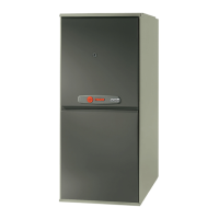
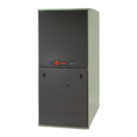
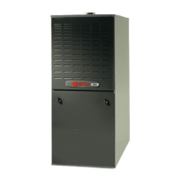
UPFLOW / HORIZONTAL and DOWNFLOW / HORIZONTAL VENTING TABLE
TABLE 7
MAXIMUM VENT LENGTH:
MODEL
MAXIMUM TOTAL EQUIVALENT FEET
2" PIPE & FITTINGS 2-1/2" PIPE & FITTINGS 3" PIPE & FITTINGS 4" PIPE & FITTINGS
*UC/*DC040C
50 80 80 130
*UC/*DC060C
50 80 80 130
*UC/*DC080C
40 80 80 130
*UC/*DC100C 30 80 80 130
*UC/*DC120C
NOT ALLOWED 25 70 130
NOTES:
* - First letter may be "A" or "T"
1.
DO NOT MIX PIPE DIAMETERS IN THE SAME LENGTH OF PIPE OUTSIDE THE FURNACE CABINET
(Except adapters at top of furnace).
2.
MAXIMUM PIPE LENGTHS MUST NOT BE EXCEEDED!
3.
One 90° elbow is equivalent to 12' of 4" pipe. One SHORT radius 90° elbow is equivalent to 10' of 3" pipe and one
LONG radius elbow is equivalent to 6' of 3" pipe. One SHORT/LONG radius 90° elbow is equivalent to 7½' of
2½" pipe, & 5' of 2" pipe. Two 45° elbows equal one 90° elbow.
4.
The termination tee or bend must be included in the total number of elbows.
5.
Pipe adapters are field supplied. Downflow models and *UC120 include 2" X 3" adapter.
6.
4" pipe may be reduced to 3" for termination with BAYVENT100 or BAYVENT200 without length restriction
INTEGRATED FURNACE CONTROL ERROR FLASH CODES
Flashing Slow --- Normal - No call for Heat
Flashing Fast --- Normal - Call for Heat
Continuous ON --- Replace IFC
Continuous OFF --- Check Power
2 Flashes --- System Lockout (Retries or Recycles exceeded)
3 Flashes ---
Draft Pressure Error - Possible problems:
a) Venting problem
b) Pressure switch problem
c) Inducer problem
4 Flashes --- Open Temperature Limit Circuit
5 Flashes --- Flame sensed when no flame should be present
6 Flashes --- 115 volt AC power reversed, poor grounding or system voltage too low
7 Flashes --- Gas valve circuit error
8 Flashes --- Low flame sense signal

 Loading...


