16 18-CD19D5-10
Installer’s Guide
12" MIN. ABOVE
NORMALLY EXPECTED
SNOW ACCUMULATION
1" CLEARANCE
( AIR SPACE )
90˚ ELBOW
12" MIN.
PVC WALL MOUNT
FLANGE
STUD
COUPLING
( PLASTIC
VENTING )
6 IN. MIN.
(TO JOINT)
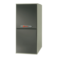
VENTING THROUGH COMBUSTIBLE WALLS
Pitch -- 1/4 Inch Per Ft.
CLEARANCE ( 0" ACCEPTABLE FOR PVC VENT PIPE )
( 1" ACCEPTABLE FOR TYPE 29-4C STAINLESS STEEL VENT PIPE )
a
s
The vent/wind terminal must terminate at least 3' above any
forced air inlet into the building that is within 10' of the terminal.
The terminal must also terminate 4' below, 4' horizontal from or 1'
above any door, window or other air inlet into building.
The vent/wind terminal shall not terminate over public walk-
ways or over an area where condensate or vapor could create a
nuisance or hazard or could be detrimental to the operation of
regulators, relief valves, or other equipment.
The vent/wind terminal shall have a minimum horizontal
clearance of 4' from electrical meters, gas meters, regulators,
and relief equipment.
PITCH – Venting through the wall must maintain 1/4" per foot
pitched upward to insure that condensate drains back to
furnace.
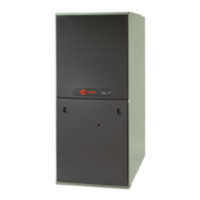
FLUE GAS DEGRADATION – The moisture content of the
flue gas may have a detrimental effect on some building materi-
als. This can be avoided by using the roof or chimney venting
option. When wall venting is used on any surface that can be
affected by this moisture, it is recommended that a corrosion
resistant shield (24 inches square) be used behind the vent
terminal. This shield can be wood, plastic, sheet metal, etc. Also,
silicone caulk all cracks, seams and joints within 3 feet of the
vent terminal.
d
HORIZONTAL
VENT CAP
BAY69X146
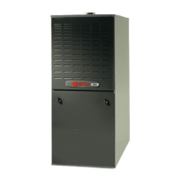
VENTING THROUGH NON-COMBUSTIBLE WALLS
Pitch – 1/4 Inch Per Ft.
12" MIN. ABOVE
NORMALLY EXPECTED
SNOW ACCUMULATION
CEMENT
MORTAR SEAL
INSIDE &
OUTSIDE
90˚ ELBOW
12" MIN.
COUPLING
( PLASTIC
VENTING )
PVC WALL MOUNT
FLANGE
6 IN. MIN.
( TO JOINT )
NONCOMBUSTIBLE MATERIAL WALL
The hole through the wall must be large enough to maintain
pitch of vent and properly seal.
Use cement mortar seal on inside and outside of wall.
See Figure 23.
COMBUSTIBLE MATERIAL WALL
A minimum clearance of 1" to combustible materials must be
maintained when using single wall stainless steel venting. See
Figure 22.
Shield material to be a minimum of 24 gauge stainless or
aluminized sheet metal. Minimum dimensions are 12"x12".
Shield must be fastened to both inside and outside of wall. Use
screws or anchor type fasteners suited to the outside or inside
wall surfaces. See example in Figure 21.
 Loading...