Installation
RT-SVX26K-EN 27
Use the following checklist in conjunction with the general
checklist (“General Unit Requirements,” p. 19) to ensure
that the unit is properly installed and ready for operation.
• Check all electrical connections for tightness and
“point of termination” accuracy.
• Verify that the condenser airflow will be unobstructed.
• Verify that the condenser fan and indoor blower turn
freely without rubbing and are properly tightened on
the shafts.
• Check the supply fan belts for proper tension and the
fan bearings for sufficient lubrication. If the belts
require adjustment, or if the bearings need lubricating,
refer to the maintenance section of this manual for
instructions.
• Verify that a condensate trap is installed and the piping
is properly sized and pitched.
• Verify that the correct size and number of filters are in
place.
• Inspect the interior of the unit for tools and debris and
install all panels in preparation for starting the unit.
Voltage Imbalance
Three phase electrical power to the unit must meet
stringent requirements for the unit to operate properly.
Measure each leg (phase-to-phase) of the power supply.
Table 7. Gas heater operating data
Heating Input Rate—Btu/h
(a)
(a) For 50 Hertz applications, multiply rated Btu/h by 83 percent.
135,000 205,000
Minimum Supply Gas Pressure Natural/
LP
3.5” w.c./ 8.0” w.c.
Manifold Gas Pressure
(b)
(b)Staged gas heat units have a negative pressure gas valve. Never adjust
the staged gas pressure valve to a positive pressure.
-0.2” w.c
Combustion Blower Suction Pressure (1
st
Stage)
-2.1 to -3.1”
w.c.
-0.8 to -1.2”
w.c.
(With Gas Valve Closed) (2
nd
Stage) N/A -2.1 to -3.1” w.c.
Minimum Flame Sensing Current
(c)
(c) A voltage reading across pens (V+) & (V-) is equatable to the flame sens-
ing current. One volt equals one micro amp.
5.0 Microamps D.C.
Normal Sensing Current Range 8.0 to 16.0 Microamps D.C.
Flue Gas Temperature Rise Above
Ambient
400°F to
500°F
350°F to
475°F
Flue Gas Content - %CO
2
8.3 to 9.5 8.0 to 9.0
Natural LP 9.5 to 10.5
Minimum Supply Air Temperature Across
Heat Exchanger
40°F
Table 8. Piping
Length of
Pipe (ft)
Iron Pipe Size (IPS) Inches
½” Pipe ¾” Pipe 1” Pipe 1¼” Pipe 1½” Pipe
15 76 176 345 750 1220
30 52 120 241 535 850
45 43 99 199 435 700
60 38 86 173 380 610
75 - 77 155 345 545
Note: Capacity of Pipe of Different Diameters and Lengths in Cu. Ft. Per
Hr. with Pressure Drop of 0.3" and Specific Gravity of 0.60
Table 9. Specific gravity multipliers
Specific Gravity Multipliers
0.50 1.10
0.55 1.04
0.60 1.00
0.65 0.96
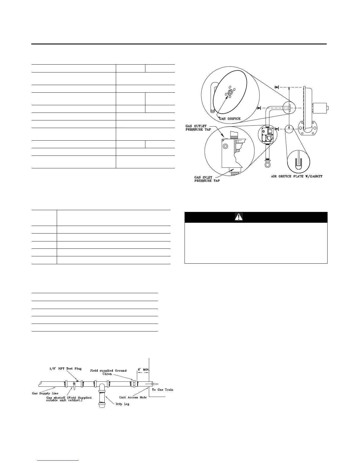
Figure 19. Schematic diagram for field gas piping to
units
Figure 20. Typical unit gas train configuration
WARNING
Hazardous Voltage!
Disconnect all electric power, including remote
disconnects before servicing. Follow proper lockout/
tagout procedures to ensure the power can not be
inadvertently energized. Failure to disconnect power
before servicing could result in death or serious injury.
 Loading...


