6
WTK-SVN001-EN
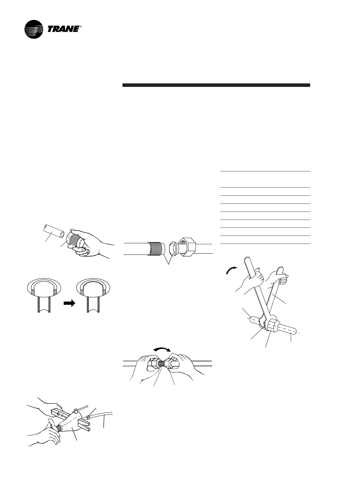
Connection of Refrigerant Tubing
Flare nut
Copper
tubing
Flare tool
Figure 4
Figure 2
Copper tubing
Reamer
Figure 3
Before After
Figure 5
Apply refrigerant lubricant here
Figure 6
Union Flare nut
A good flare should have the
following characteristics:
-Inside surface is glossy and smooth.
- Edge is smooth.
-Tapered sides are of uniform length.
Cautions Before Connecting
Tubes Tightly
1. Be sure to apply a sealing cap or
water-proof tape to prevent dust
or water from getting into the
tubes before they are used.
2. Be sure to apply refrigerant
lubricant to the matching surfaces
of the flare and union before
connecting them together. This is
effective for reducing gas leaks
(Figure 5).
4. Tighten the flare nut to the specified
tightening torque with torque
wrench and adjustable wrench
(Figure 7).
5. Repeat the process above for
the remaining line.
Connection the Unit with Flaring
Procedure
Flaring (If tubing is procured or cut
at the site).
1. Cut the copper tube to the
required length with a tube cutter.
It is recommended to cut approx.
30 cm-50 cm (12” to 20”) longer
than the tubing length you estimate.
2. Hold each tube downward when
cutting, remove burrs at the end of
the copper tube with a tube reamer
or file. This process is important
and should be done carefully to
make a good flare (Figure 2 and
Figure 3).
When reaming, hold the tube end
downward and be sure that no
copper scraps fall into the tube.
3. Remove the flare nut from the
service valve and be sure to insert
the flare nut onto tube.
4. Make a flare at the end of copper
tube with a flare tool (Figure 4).
Connection
3. For proper connection, align the
union tube and flare tube straight
with each other, then screw in the
flare nut lightly at first to obtain a
smooth match (Figure 6).
Indoor
unit pipe
Torque wrench
Flare nut
Tube connection
Wrench
(Adjustable)
Figure 7
Specified tightening torque
Tube diameter Torque
mm inch kg - cm lb - in
6.35 mm (1/4”) dia. 150~200 130~170
9.53 mm (3/8”) dia. 350~400 300~340
12.7 mm (1/2”) dia. 500~550 430~470
15.88 mm (5/8”) dia. 600~650 520~570
19.05 mm (3/4”) dia. 700~750 610~650
22.23 mm (7/8”) dia. 800~850 700~740
28.58 mm (1-1/8”) dia. 900~950 800~825