© Copyright 2014 TRENDnet. All Rights Reserved.
TRENDnet User’s Guide
TPE-224WS
3
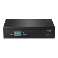
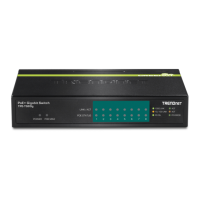
• PoE LED button mode
When the PoE powered device (PD) is connected and
the port supplies power normally.
PoE port has may have one of the following issues:
PoE power circuit shortage.
Power over current: over the power current of
PD’s classification.
Out of PoE voltage of 44 ~ 57 VDC output.
No PoE powered device (PD) connected or unplugged
the PoE output port. No power is supplied.
• Gigabit Ports 25-28
• Link/ACT LED button toggle mode only
When the Green LED lights on, the link is established at
When the Amber LED lights on, the link is established at
10/100Mbps.
Blinking :
When the
LED is blinking, the port is transmitting or
receiving data.
Off The link is disconnected or not established.
• Shared SFP Slots 25F-26F
• Link/ACT LED button toggle mode only
When the Green LED lights on, the link is established at
When the Amber LED lights on, the link is established at
100Mbps.
Blinking :
When the
LED is blinking, the port is transmitting or
receiving data.
Off The link is disconnected or not established.
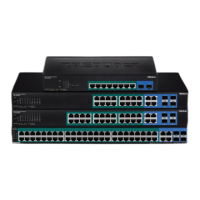
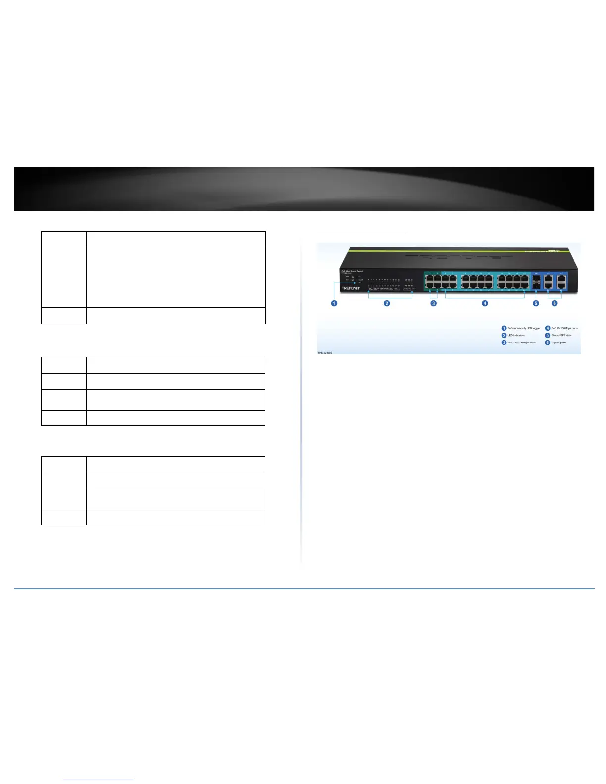
Application Diagram
The PoE WebSmart switch can be installed a server room within an EIA standard-size, 19-inch
rack or placed on a desktop.
The PoE+ switch supplyies power and provides data connectivity
through the Ethernet cable to PoE/PoE+ devices (such as wireless access points, IP cameras, and
other PoE/PoE+ devices) using ports 1-24. Ports 1-4 can supply up to 30W (802.3at PoE+) and
ports 5-24 can supply up to 15W (802.3af PoE). The switch also provide a toggle button to switch
the LED display for link/act port connectivity or PoE. The switch can connect the PoE devices to
your network through the non-PoE Gigabit Ethernet uplink ports (25-28) to a switch that is
connected to your network. Optionally, you can use the shared SFP slots (25F-26F) as
uplinks/downlinks for longer distance installations.