page -32
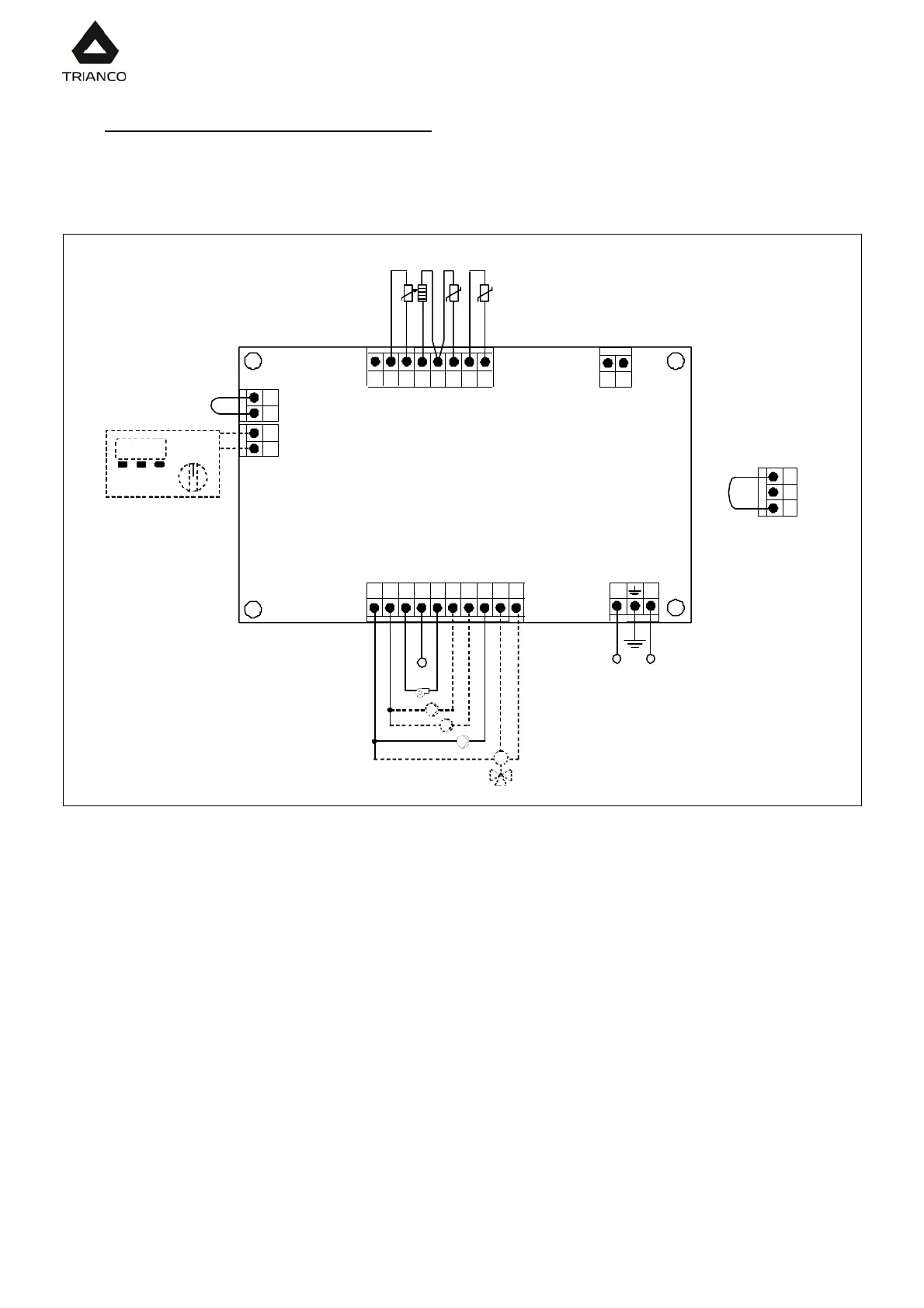
21.- ELECTRICAL CONNECTION DIAGRAM
There are a series of removable connectors located on the rear of the control panel, for
connecting the various options and components for this model. For correct connection,
carefully follow the indications shown below:
1 86543NNN 7
J1J2
J4
N F
Q
J5
A
1
E20
BV
2
220 V
J7
A
2
bc7
Black
Blue
Blue
Blue
Brown
BC
2
BC
1
M
J6
191817
6
15
J3
Sc
Blue
RaRr
Blu e
PWM
c
Blu el
14131
9
+
(-)
Ph: Phase.
N: Neutral.
bc7: Burner terminal n. 7.
Q: Burner.
BV: DHW charge pump.
BC
1
: Heating circuit N. 1 circulating pump.
BC
2
: Heating circuit N. 2 circulating pump.
M: Underfloor 3 way valve motor.
E20: Remote control E20 (optional).
TA
1
: Heating circuit N. 1 room thermostat.
TA
2
: Heating circuit N. 1 room thermostat.
PWM
c
: Heating PWM cable.
Rr: Underfloor heating option resistance.
Ra: Storage tank option resistance.
Sc: Boiler temperature sensor.
J1: Power supply connector.
J2: Components connector.
J3: Sensor connector.
J4: Remote control connector.
J5: Room thermostat N. 1 connector.
J6: Telephone relay connector.
J7: Room thermostat N. 2 connector.