Do you have a question about the TRIATEK FMS-2000C and is the answer not in the manual?
Warning about high voltage components causing shock or injury.
Caution for use in controlled environments; refer to installation instructions.
Warnings regarding wiring, power sources, and network cables.
Notes on environmental conditions, qualified personnel, and Triatek products.
Use copper conductors and adhere to electrical ratings and regulations.
Do not install where temperatures exceed 125°F (52°C) to avoid damage.
Follow electrical codes, local regulations, and use ESD precautions.
Maintain correct polarity, voltage, and current ratings to avoid voiding warranty.
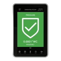
Ensures safe settings by monitoring pressure, airflow, temp, humidity, CO2, ACH.
Color-coded alarms, 360° Safety Halo, audible alarm mute, password protection.
Controller placement, display location options, and sensor placement advice.
Step-by-step guide and tools required for mounting the display in a retrofit application.
Detailed instructions for mounting the display in a new installation.
Lists the necessary tools for installing the display in a new application.
Detailed steps for installing the remote sensor module and flow tube.
Guidance on determining sensor location and required tools for mounting.
Explanation of symbols used in wiring diagrams.
Diagram showing the back plane connections of the controller.
Illustration of the wiring on the interior front housing of the controller.
Table detailing the function of various DIP switches for controller configuration.
Diagram illustrating the electrical connections between the display and controller.
Instructions for updating an FMS-1655 display to the FMS-2000C.
Wiring diagram specific to the FMS-1655 to FMS-2000C retrofit.
Diagram and settings for wiring an analog output to a pneumatic damper actuator.
Diagram and settings for wiring an analog output to a variable speed drive.
Diagram for wiring a single remote pressure sensor (4-20mA).
Configuration settings for analog inputs related to remote sensors.
Diagram for wiring two remote pressure sensors (4-20mA).
Diagram for wiring three remote pressure sensors (4-20mA).
Diagram for wiring four remote pressure sensors (4-20mA).
Diagram for wiring a third-party sensor, including configuration options.
Diagram for connecting temperature sensors or thermistors.
Diagram illustrating wiring connections for a room thermostat.
Diagram for wiring precision temperature sensors.
Diagram and settings for connecting a door switch as a digital input.
Diagram and settings for connecting an occupancy sensor as a digital input.
Diagram for wiring a relay output to function as an alarm.
Diagram for wiring a relay output to function as a warning.
Diagram for wiring relay output 1, e.g., for heating stage 1.
Diagram for wiring relay output 2, e.g., for heating stage 2.
Diagram showing how to connect the power supply to the controller.
Important notes on maintaining consistency when daisy-chaining 24 VAC controllers.
Diagram and details for wiring a 120/240V to 24V stepdown isolation transformer.
Diagram and details for wiring a 24V to 24V isolation transformer.
Diagram for connecting the controller via BACnet MS/TP.
Diagram for connecting the controller via Metasys N2 open protocol.
Configuration options for the display module using DIP switch S2.
Configuration of analog inputs using DIP switch S1.
Configuration of analog outputs using DIP switch S3.
Configuration of network settings using DIP switch S3.
Detailed table of analog input configurations based on DIP switch S1.
Settings for selecting communication protocols like Metasys N2 and BACnet.
Configuration for analog outputs (S4) and network termination (S3).
Configuration options for slide switch S5 related to digital input triggering.
Lists BACnet objects for analog inputs and outputs.
Lists BACnet objects for binary inputs and outputs.
Details analog values available for BMS integration.
Further details on analog values for BMS integration, including setpoints and overrides.
Lists multistate objects for BMS integration, such as alarm and mode status.
Lists Metasys N2 objects for analog inputs and outputs.
Lists Metasys N2 objects for binary inputs and outputs.
Details internal float values for Metasys N2 integration, including setpoints.
Further details on internal float values for Metasys N2 integration, including alarm setpoints.
Lists internal integer values for Metasys N2 integration, such as alarm status.
Details on intended use, altitude, pressure, accuracy, and display.
Information on universal inputs, thermistor inputs, digital inputs, and outputs.
Details on operating temperature, humidity, and mounting options.
Information on alarm indication, silence, password protection, and protocols.
Details on power consumption, display/controller dimensions, and compliance.
Table listing features and corresponding code letters/numbers for ordering.
Steps for safely cleaning the display surface.
FCC and Canadian compliance statements for the device.
| Category | Controller |
|---|---|
| Manufacturer | TRIATEK |
| Model | FMS-2000C |
| Protection Class | IP20 |
| Weight | 1.5 kg |
| Input Voltage | 100-240 VAC, 50/60 Hz |