MONITOR LEVEL
LEVEL
5
0
5
10
15
20
25
30
40
SOLO
ACTIVE
2TRK 1
2TRK 2
STEREO
IN
ALT
MON
OUT
SUM
MONO
DIM
TB
LEVEL
TB MIC
TALK TO
GROUPS
TALK TO
AUXES
MONITOR INPUTS
LEVEL
HEADPHONE
SOLO MASTER
LEFT/RIGHT
INSERT ON
MONITOR LEVEL
ACTIVE
2TRK 1
2TRK 2
STEREO
IN
ALT
MON
OUT
SUM
MONO
DIM
TB
LEVEL
TB MIC
TALK TO
GROUPS
TALK TO
AUXES
MONITOR INPUTS
HEADPHONE
SOLO MASTER
LEFT/RIGHT
INSERT ON
Trident 68 Owners Manual15
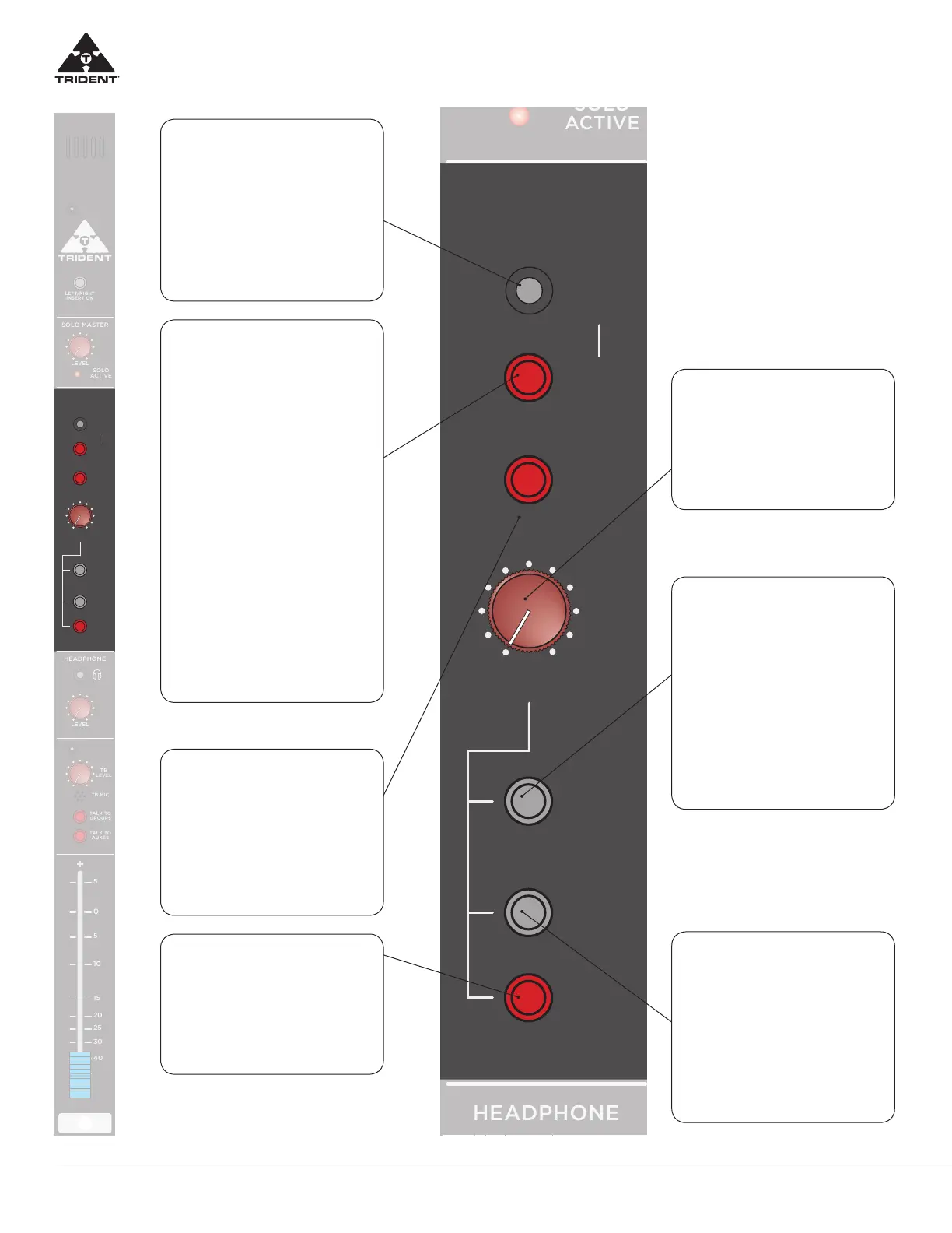
Trident 68 Master Monitor Section
STEREO IN JACK
(3.5mm, 1/8”)
This jack allows the engineer to plug in
an external stereo signal via a standard
1/8” wire cable ( i.e iPod) which can
then be selected to the main Control
Room Monitors. To assign this signal
into the main monitors, the user has to
depress the 2-TRK 1 switch.
2-TRK 1
When depressed this selects either the
signal from the stereo 2-TRK 1 Return
pins of the DSUB (on the rear master
connector panel) or the stereo sig-
nal plugged in the STEREO IN JACK
(above) and feeds it to the control
room monitors. The stereo 2-TRK 1 re-
turn signal from the rear connector is
normalled to the STEREO IN JACK sig-
nal and if a signal wire is plugged into
the STEREO IN JACK it replaces the
signal from the 2-TRK 1 Return from the
rear panel and that is the signal that is
switched to the main monitors. Note:
When this switch is depressed, the
main Left/Right mix is disconnected
from the control room monitors, also
if 2-TRK 2 switch is depressed (below)
this kills the 2-TRK 1 signal to the con-
trol room monitors. For monitoring
signals into control room monitors
the Priority is SOLO mix Ú 2-TRK 2
Ú 2-TRK 1 ÚMain Left/Right mix.
2-TRK 2
When depressed this selects the sig-
nal from the stereo 2-TRK 2 Return
pins of the DSUB (on the rear mas-
ter connector panel) to the control
room monitors. This switch has pri-
ority over 2-TRK 1 switch above. (see
description 2 TRK 1 above)
DIM
When depressed, this reduces the
level of the main monitor outputs by
approx 30 dB. Note: this has no ef-
fect on the main Left/Right outputs
of the console.
MONITOR LEVEL
CONTROL
This control adjusts the level of the
stereo signal feeding the control
room monitors and Alternate moni-
tor outputs if selected.
ALT MON OUT
When this switch is depressed the
main Left/Right Monitor feed is di-
verted to the ALT MONITOR output
pins of the associated DSUB on the
rear connector panel. In doing so,
the console main Left /Right monitor
signal is switched OFF.
This allows the engineer to set up a
separate monitor feed (say to another
set of monitor speakers) and be able
to A/B the systems for comparison.
SUM MONO
Combines the Left and Right signals
feeding the control room monitors
to produce a summed (L+R) mono
signal that feeds both Left and Right
monitor outputs. Note: The SUM
MONO facility is purely a monitor
function and does NOT aect the
main stereo Left/Right output which
remains as a true stereo image.