EasyManua.ls Logo

trig TT21 - Tt21;Tt22 Transponder Electrical Connections; TT21;TT22 Interface - Pinout

trig TT21
69 pages
Print Icon
To Next Page IconTo Next Page
To Previous Page IconTo Previous Page
Loading...
TT21/TT22 Transponder Installation Manual 22 August 2017
00560-00 AP
______________________
14 Trig Avionics Limited
close proximity to other avionics. The reliability of equipment operating in
close proximity in an avionics bay can be degraded if adequate cooling is not
provided.
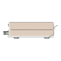
5.5 TT21/TT22 Transponder Electrical Connections
The TT21/TT22 has a single 25 way female socket which provides the data
and power inputs to the transponder. A single TNC coaxial connector attaches
to the antenna.
5.5.1 TT21/TT22 Interface Pinout
Pin
Signal
Direction
1
Ground
-
2
TMAP1A
Bidirectional
3
TMAP1B
Bidirectional
4
Ground
-
5
GPS Position In
Input
6
Ground
-
7
TIS Traffic Out
Output
8
TMAP2A
Bidirectional
9
TMAP2B
Bidirectional
10
Ground
-
11
Controller Power
Output
12
Ground
-
13
Power ON
Input
14
Ground
-
15
11-33V DC
Input
16
Reserved
-

Table of Contents

Other manuals for trig TT21

Related product manuals