TT21/TT22 Transponder Installation Manual 22 August 2017
00560-00 Issue AP
______________________
Trig Avionics Limited 15
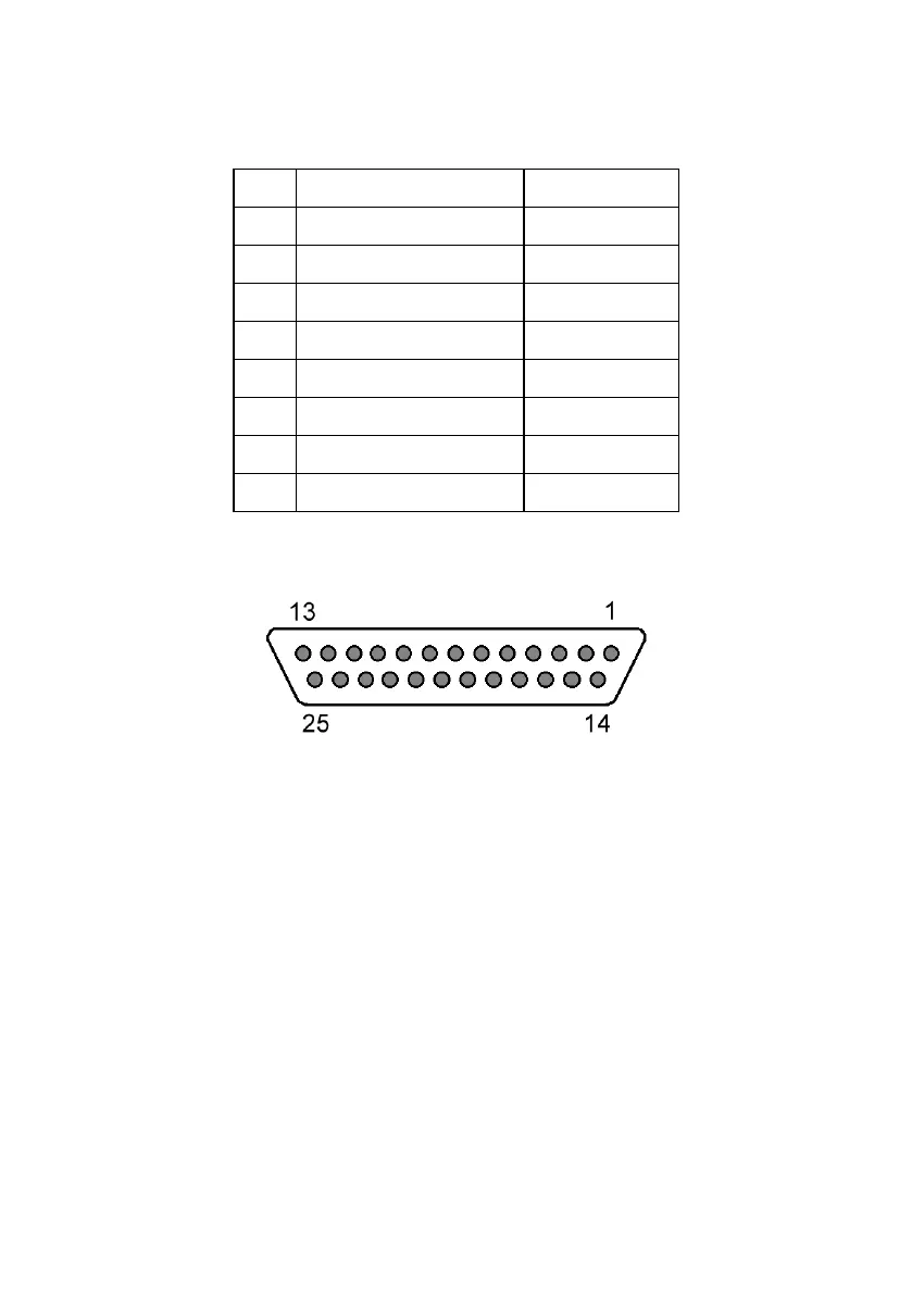
The following diagram shows the connector orientation as viewed from the
wiring side.
5.6 TT21/TT22 Transponder Interface Details
5.6.1 Power Input
The power supply can be 11-33 Volts DC; no voltage adjustment is required.
Use a 3 Amp circuit breaker for power supply protection to the TT21/TT22.
It is always good practice to use more than one ground wire in an installation.
This is particularly important when the transponder is mounted on a non-
conducting surface, such as a composite structure. With only one wire there
could be only a single grounding path for the transponder, controller and
antenna.
Note: The transponder power input is not protected against reversed