6
ERROR DISPLAY CODES
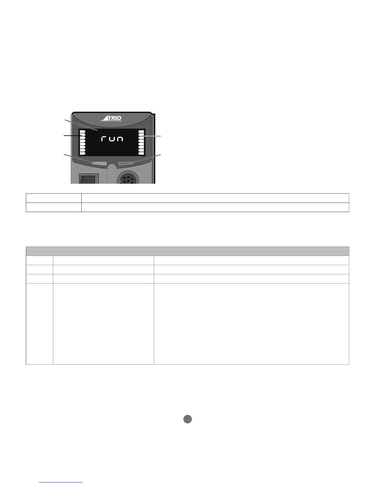
The information display area shows the IP address and subnet mask during power-up and whenever an Ethernet cable is rst
connected to the MC664. During operation, this display shows run, O or Err to indicate the MC664 status. Below the main
status display are the ERROR and ENABLE indicators.
ERROR An error has occurred (see Error Display Codes table below for details).
ENABLE When illuminated, WDOG is ON.
A bank of 8 indicators at the left side shows the Digital Input States and a similar bank on the right shows the state of I/O8 to I/
O15. The I/O displayed can be altered using the DISPLAY command.
Two LED’s are provided to show the processor (OK) and system status.
Error Display Codes
Unn Unit error on slot nn ie: EtherCAT failed to start
Ann Axis error on axis aa ie: following error exceeds limit
Caa Conguration error on unit aa ie: too many axes
Exx System error
E00 - RAM error 8bit BB - RAM (VR)
E01 - RAM error 16 bit BB - RAM (TABLE)
E04 - VR/TABLE corrupt entry
E05 – Invalid MC_CONFIG le
E06 – Started in SAFE mode (system timeout)
E07 - FPGA Error
E08 - Flash memory error
E09 - Processor Exception
E10 - RFID chip access failed