6
INSTALLATION OF EQUIPMENT
The installation of the equipment should only be carried out by engineers who
are trained in fitting standard pool filtration equipment.
BOOSTER PUMP & INJECTOR
The injector booster pump suction pipe should be installed as close as possible
to the main pool water return line.
The pump MUST be installed in such a manner that it has flooded suction at all
times as failure to do so will result in a premature failure of the pump seals.
The pipework should be sized to suit the suction and discharge of the pump used
and incorporate isolation valves at both take-off connections to the main pool
water return line and also between the booster pump discharge and the injector.
The injector can be mounted either in a horizontal or vertical position. It is
normally mounted directly above the booster pump discharge valve.
WATER TRAP ASSEMBLY
water trap assembly, as shown in the typical installation diagrams, MUST
always be used to ensure that water cannot pass from the injector to the ozone
generator when the water booster pump is stopped.
The water trap assembly should be wall mounted as close as possible to the
injector at a distance not exceeding 3 metres and at the height indicated.
fter mounting, the injector suction should be connected to the top connection o
the water trap assembly utilising the flexible tubing supplied. The tubing should
be clipped to the wall at 300mm centres to prevent the tubing from kinking unde
it’s own weight, particularly at the top connection to the water trap.
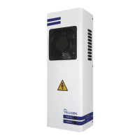
OZONE GENERATOR
The ozone generator should be wall mounted as close as possible to the wate
trap assembly at a distance not exceeding 3 metres and a minimum height o
1.65 metres above floor level.
The ozone generator MUST only be wall mounted utilising the two screw fixings
included with the unit.
When the position of the ozone generator has been ascertained, the two holes
centres should be marked and drilled in accordance with the fixing centres of the
unit. Insert the plastic rawlplugs into the drilled holes and then insert the
roundhead screws until the screw head is protruding 3mm above the surface.
The ozone generator is then hung on the screw fixings utilising the keyhole slots
on the rear of the unit.