The Guided Pushstick slides in the
T-slot on the 45˚ face of the rip
fence. The swing-arm rests against
the vertical face, and should pivot
freely.
The lock direction of the swing-arm
can be reversed (depending on
which side of the Workcentre the
rip fence is used) by firmly pressing
the direction switch.
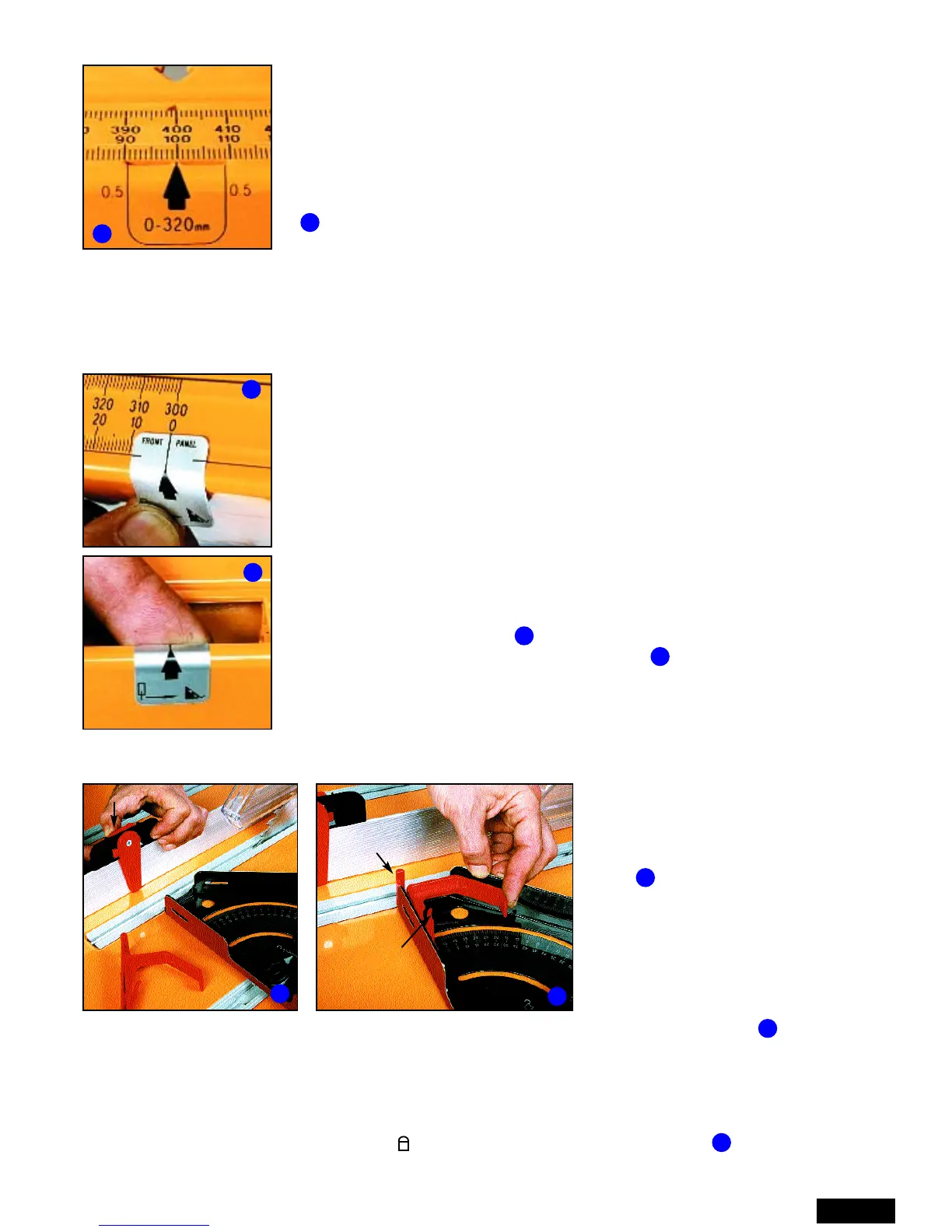
Clip the Side Pressure Finger to the holder, noting the correct orientation of the bulge . Snap the
assembly into the left-hand corner of the protractor. Pull the finger out to lock. Press the trigger and
push the finger in to retract.
In use, the finger is extended and the protractor locked at an appropriate angle to press the wood
against the fence in front of the blade. The protractor must be locked in it’s slot by loosening the
locking knob, rotating the pointer to the position, and re-tightening. (See also Page 12)
A spare finger is included in case you accidentally cut one.
Page 11
Set on the left of the blade, the fence gives the maximum 620mm capacity.
However, if you prefer to use the fence on the right, the self-adhesive
Scale Pointer Labels (u), will provide the zero position.
Fit the fence on the right and touch it against the blade. Check it is exactly
parallel by comparing the readings at the front and rear panels - about
183mm / 483mm. Lock the fence, turn the blade backwards by hand and
the teeth should lightly skim the fence.
Remove all dust, and apply the labels to the specified end panels directly
in line with the 0 marks on the scale arms.
The labels wrap inside the tracks to prevent peeling off. Lines printed on
the labels show where to fold. Once they’re stuck in position, slide the
fence away to fold the tops of the labels inside.
The edges of the pointer cutout, and the two fine 0.5 lines are 9.5mm from the arrow-point. Use
them as a vernier in setting 0.5 mm increments, to avoid guessing the mid-point between
graduations.
USING THE RIP FENCE SCALES
USING THE RIP FENCE ON THE RIGHT
You can reverse the bolt and knob in the overhead guard for closer fence
access if using the fence on the right.
2
3
2
3
FITTING THE GUIDED PUSHSTICK AND SIDE PRESSURE FINGER
4
5
Direction switch
Note direction
of bulge
4
Trigger
5
1
Each end panel has two scale pointers exactly 300 mm apart. For cuts in
the range 0 - 320, (with the fence on the left of the blade) use the pointers
which are closer to the blade. Line up the arrow point and read the lesser
figure on the scale arms.
For wider ripping in the range 320 - 620mm simply move across to the
outer scale pointers and read the higher figure.
In , the fence is set at 100mm using the 0-320 mm pointers. It would be
400 mm if you were using the outer pointers.
1
6