Power Shower
16
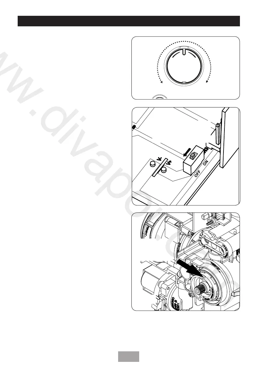
In order to dispel air and to prime both supplies
to the shower unit, turn the temperature control
several times within its rotational limits.
Note: The temperature control is fitted with
a maximum temperature stop, pressing the
override is required to achieve fully hot position.
(fig.21). ONCE RESISTANCE IS FELT, DO
NOT FORCE THE CONTROL FURTHER.
To stop the water flow, press the start/stop
button to switch off the unit and isolate the
electricity supply at the isolating switch. Remove
the temperature control knob and front cover
assembly, unplugging the 8 way connector lead
from the PCB and carefully put both aside.
Check for leaks in the pipework and remedy
if necessary. If rear entry has been used then
seal around pipes with mastic to prevent the
possibility of water entering the wall cavity. DO
NOT use plaster as this could cause difficulties if
maintenance is required at a later date.
Set up Procedure
On the PCB, position the dip switch to the OFF
position to allow pump operation (fig.22).
Check the maximum temperature stop is still in
position at 12 O'clock (fig.23).
Make sure the start/stop button on the front
cover assembly is in the OFF position (flush
with the cover). Attach the 8 way connector
lead to the 8 way pins on the PCB (refer back
to fig.19) and offer the front cover assembly
to the unit. Ensure the wires are clear of the
front cover assembly and secure with the screws
provided.
Switch the electricity supply back on at the
isolating switch. Make sure both water supplies
are still turned on.
Once the installation of the riser rail is complete,
the shower will be ready for temperature control
set up and then normal operation.
Commissioning OFF
(switch in DOWN position)
Pump will operate
Fig.22
3 O’clock
postion
12 O’clock
postion
Temperature overtravel
press button and turn
knob anti-clockwise
Fig.23
Hot Cold
Fig.21
www.divapor.com




 To Next Page