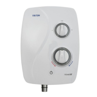
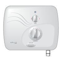
Power Shower
9
Under no circumstances should this product
be connected to mains cold or hot water
supplies. Failure to comply will invalidate the
guarantee.
GENERAL INSTALLATION NOTES
1. DO NOT take risks with plumbing or
electrical equipment.
2. Isolate electrical and water supplies BEFORE
proceeding with installation work.
3. Shower control MUST be fed from a cold
water storage cistern and hot water cylinder
that provides nominally equal pressures.
4. If installing with rear inlet supplies, it is
recommended the supply pipework is sealed
to the wall so as to prevent water from
leaking back into the wall.
5. In solid wall installations, the supply
pipework should be housed within
ducting in order to allow some free lateral
movement when making connections and
to ensure compliance with requirements of
accessibility of pipes and pipe fittings.
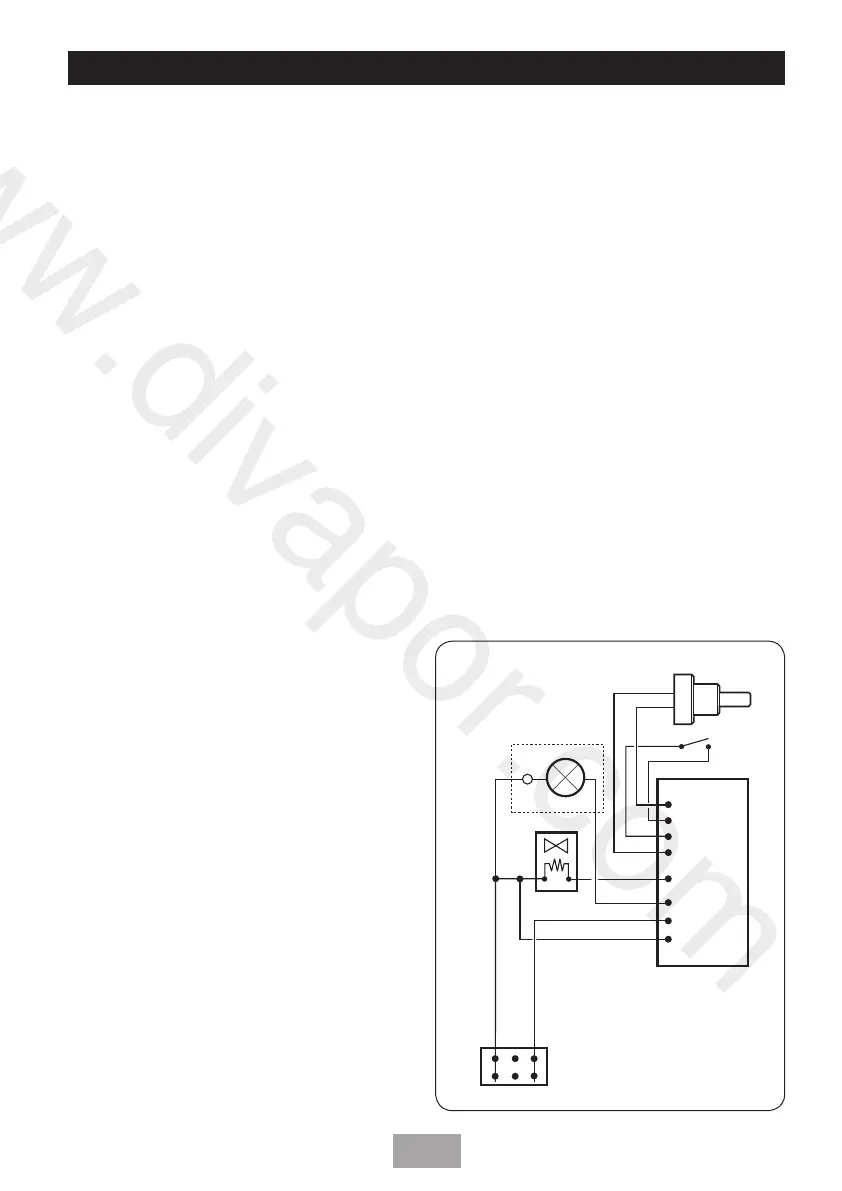
Fig.4 shows a schematic wiring diagram of the
unit.
SITE REQUIREMENTS
Water
The installation must be in accordance with
Water Regulations/Bylaws and BS-EN 806.
For correct operation of this shower unit, both
hot and cold water supplies to the appliance
must be gravity fed, at nominally equal
pressures, from a cold water storage cistern
and a hot water storage cylinder. The water
circuit should be installed so that the flow is
not significantly affected by other taps and
appliances being operated elsewhere on the
premises.
Fig.3a shows a recommended installation where
the hot water supply for the shower is made
via a tee connection on the underside of the
horizontal section of pipework from the
cylinder. Alternatively, the connection can be
taken from the hot supply pipe to other outlets
as long as it is the first draw-off below the
ventilation pipe tee.
IMPORTANT: Failure to conform to Fig.3a
can allow air ingress into the product which
can impair performance and may invalidate the
guarantee.
Fig.3b illustrates incorrect connections that
must be avoided.
All pipework to the shower unit must be routed
where it remains below the level of water in
the cistern. In the case of horizontal sections
of pipework in lofts, it may be necessary to
fit automatic air vents at high points on the
supplies to remove the possibility of air locks.
For the operation of the shower only, it is
recommended that the cold water storage
cistern is capable of holding at least 114 litres
(25 gallons). Where other hot and cold outlets
are likely to be in use simultaneously, the storage
capacity should be increased to 228 litres (50
gallons) in accordance with BS-EN 806.
DO NOT connect to a combination cylinder
unless there is a guaranteed 114 litre cold supply
to the cylinder as the shower can deliver up to
14 litres per minute. It is advisable to check that
the infill rate from the float operated valve meets
the output requirements. It is recommended
that there is a minimum of approximately 114
litres (25 gallons) of hot water storage per
appliance.
L E N
Potentiometer
Switch
Solenoid
Motor
PCB
Thermal
fuse
Fig.4
www.divapor.com
 Loading...