Do you have a question about the Triton OMNICARE ULTRA and is the answer not in the manual?
Warning that failure to use genuine Triton parts may cause injury and invalidate the guarantee.
The shower unit must be switched off at the isolating switch when not in use for safety.
Please read this book thoroughly and familiarise yourself with all instructions before commencing installation.
The shower installation MUST be carried out by a suitably qualified person, in the sequence of this instruction book.
Do not operate the shower if there is a possibility of frozen water within the heater or pipes.
Do not operate the unit if the showerhead or spray hose becomes damaged.
Do not restrict water flow by placing showerhead in direct contact with body or surface.
Do not operate if water flow stops or water enters unit due to incorrect cover fit.
Be aware of a slug of hot water expelled for first few seconds when restarting shower.
The spray head must be descaled regularly to prevent restrictions.
Fit only manufacturer-recommended shower heads and hoses to avoid flow restrictions.
The outlet must not be connected to any tap or fitting other than those specified by the manufacturer.
Appliance intended for permanent connection to water mains, not by hose set.
Water inlet must be connected to mains cold water only.
This appliance is not to be used for a potable water supply.
A suitable double pole isolation switch must be incorporated in the fixed wiring circuit.
Specifies minimum 100kPa (1 bar) and maximum 1000kPa (10 bar) inlet pressure.
Children aged 3+ can use with supervision; they must not play or maintain the appliance.
Isolate electrical and water supplies before removing the cover or proceeding with installation.
Read all instructions and retain them for later use.
Do not take risks with plumbing or electrical equipment.
Mount on finished wall surface; do not tile up to or seal around the unit.
Contact Customer Experience for issues like incorrect pressure or performance changes.
Consider a scale inhibitor for operation in hard water areas (above 200 ppm).
Regularly clean the showerhead with descalent to prevent flow restrictions.
Product is not suitable for steam rooms, cubicles, or exposed outdoor elements.
Do not solder fittings near the unit to prevent heat damage to components.
Do not fit outlet flow controls as the outlet acts as a vent.
Do not use excessive force on connections; finger tight is sufficient for hoses/showerheads.
Complete all plumbing connections before making electrical connections.
Appliance must not be connected to the inlet supply by a hose-set.
Installation must comply with BS 7671 (IEE wiring regulations) and building regulations.
This appliance must be earthed.
Appliance intended for permanent connection to the fixed wiring system.
Ensure all electrical connections are tight to prevent overheating.
A 30mA RCD must be installed in all UK electric shower circuits.
Switch off immediately at isolating switch if water ceases to flow during use.
Do not connect other electrical equipment to the shower unit's circuits.
Switch off at isolating switch when not in use; a recommended safety procedure.
Recommended to have shower and installation checked by an electrician every two years.
Thoroughly read and understand all instructions before commencing installation and keep for future reference.
Installation must be performed by a qualified person following the sequence in the fitting instructions.
Important advice for users to understand how the shower operates.
Essential to follow commissioning procedure; failure invalidates guarantee and can damage unit.
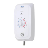
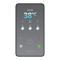
Details how temperature control adjusts between 30°C and 43°C, with restriction options.
The shower maintains temperature according to BEAB care mark specifications.
Do not place items on top of the unit as liquid seepage can cause damage.
Advised to isolate water and electricity supplies if the property is left unattended for extended periods.
Details electrical ratings, fuse/MCB, RCD, isolation switch, and cable requirements.
Outlines supply source, pressure limits, temperature, and inlet/outlet connection details.
Lists materials for backplate, cover, controls, showerhead, and elements.
Details splashproof rating, safety compliance, BEAB Care, and UKCA/CE markings.
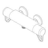
Identification of components located inside the shower unit.
Identification of components located on the inside of the shower unit cover.
Shows dimensions and water/electrical entry points for the Omnicare Ultra model.
Displays dimensions and entry points for the Omnicare Ultra+ model.
Details plumbing rules, pipe flushing, fitting types, and stop valve requirements.
Guidance on where to position the shower unit for optimal use and servicing.
Specifies water regulations on showerhead placement and potential need for check valves.
A diagram illustrating shower unit positioning, water supply, and height requirements.
Covers electrical connection rules, supply voltage, circuit protection, and cable sizing.
Chart showing cable current carrying capacity based on size and installation method.
Example of the shower's rating label showing model, voltage, power, and pressure ratings.
Details requirements for the 45A double pole isolating switch, including placement and gap.
Requirements for switch accessibility, preventing accidental contact in wet areas.
Socket outlets in rooms other than bathrooms must be RCD protected.
Cable capacity must match protection; derating affects size based on installation conditions.
Illustrates internal wiring connections for the shower unit components.
Guidance on mounting the shower unit on tiled walls, ensuring vertical alignment and access.
Information on accessing a step-by-step installation video guide on YouTube.
Instructions for removing the front cover, splashguard screws, and splashguard.
How to rotate the inlet fitting to match the water supply pipe entry point.
Complete plumbing, flush pipework to remove debris before connecting the shower unit.
Steps for marking holes, drilling, using wall plugs, and securely fixing the unit to the wall.
Check pipe fittings for tightness, use sealant for rear entry to prevent leaks.
Routing electrical cable, connecting to terminal block (L, N, E), and tightening screws.
Reattach the splashguard and secure it with the provided screws.
Position and cut cover for trunking installations to ensure a tight fit.
Instructions for connecting analogue drain pumps, explaining signal logic and wiring.
Details DIP switch settings for analogue drain pump configuration.
Instructions for connecting digital drain pumps, detailing signal logic and settings.
Explains DIP switch settings for digital pump configurations like 2200 Pulses/litre.
How to adjust shower functionality using DIP switches on the Power PCB.
Configuration for audible notifications for shower operations and warnings via DIP switch 1.
Adjusting shower run time before automatic phased shutdown using DIP switches 2 and 3.
Step-by-step guide for commissioning the shower, including water and electrical supply activation.
Connect the shower hose to the outlet, ensuring proper seal and positioning.
Temporarily fit the cover, aligning the temperature dial, and secure with a screw.
Turn on water/electricity, allow water to flow for 60s to bleed air, then isolate electricity.
Guide on how to adjust the maximum temperature setting to 41°C.
Procedure for setting max outlet temp to 41°C for BEAB Care mark compliance.
Connect the 6-way cable from the cover to the power PCB socket.
Position the cover, align the temperature selector, and secure with retaining screws.
Fit top/bottom trims and turn on the electric supply; power indicator should light.
Turn on the electricity supply at the isolating switch; check power indicator.
Initiate the shower by pressing the Start/Stop button; water will flow shortly.
Rotate the temperature control clockwise for hotter, anti-clockwise for cooler water.
Always check the water temperature before starting to shower.
Press the Start/Stop button to stop; water purges remaining hot water.
Turn off electricity supply only after water flow has stopped.
Describes the green power-on indicator light on the start/stop button.
Explains the red low flow indicator and audible beep, and how to restart the unit.
Details the yellow shutdown indicator for timed shutdowns or manual stops, including flashing and beeps.
Water flows briefly after stopping to purge hot water, preventing scalding.
Unit reduces power to elements if flow is restricted, maintaining temperature.
Over-temperature safety device disconnects power to prevent unsafe temperatures.
Crucial safety reminder to switch off the unit at the isolating switch when not in use.
Procedure for cleaning the water inlet filter to maintain shower performance, performed by a competent person.
Outlines tests for commissioning and ongoing in-service performance checks.
Explains commissioning tests establish a performance reference point.
Details commissioning tests, including checking water temp and terminal voltage.
Principle for in-service tests is to monitor performance for early deterioration detection.
Detailed steps for BEAB Care tests, including temps, voltages, and flow rates.
Checks before setting max temp: fittings, strainers, valves, and isolating valves.
Steps for recording supply voltage, outlet temp, and flow rates under varying conditions.
Indicates when service is needed if outlet water temp exceeds specified values.
Guidelines on how often in-service tests should be performed for safety.
Schedule for first in-service tests at 6-8 weeks and 12-15 weeks post-commissioning.
How to interpret test results to determine next test interval or service need.
Principle for setting future test intervals based on achieving minimal change in outlet water temp.
Troubleshooting for no water flow: power, unit malfunction, thermal cut-out.
Solutions for water being too hot: temperature control, unit malfunction.
Steps for cool/cold water: temperature control and maximum temperature selector settings.
Actions for continuous water flow: check control cable connection to PCB.
Actions for PRD operation: clean sprayplate, replace hose/PRD.
Low flow LED on, shower won't start: check water flow, blockages, filter.
Low flow LED during use, shower switches off: check flow, cooling, blockages.
Continuous flashing low flow LED, shower won't start: indicates failed flow sensor.
LEDs flash alternately on power-on, shower won't start: suggests Start/Stop PCB failure.
Simultaneous flashing LEDs, shower won't start: indicates outlet thermistor failure.
Permanent ON LEDs when power on, shower won't start: indicates faulty Power PCB.
Flashing LEDs and alarm indicate NTC safety device operation.
Note: identify cause before fitting new PRD unit and follow commissioning.
Electrical maintenance and repairs should be performed by a qualified person.
Procedure for faults/complaints: contact Customer Experience, engineer visit, proof of purchase.
Requirements for service visits: provide details, ensure access, proof of purchase.
Details charges for non-product faults, missed appointments, or out-of-guarantee calls.
Information on spare parts availability, ordering, and payment methods.
Guarantee for UK installations only, excludes commercial use; does not affect statutory rights.
Product guaranteed for 2 years against manufacturing defects if installed by a competent person.
Lists guarantee exclusions: misuse, incorrect installation, wear, foreign objects, consequential loss.
| Type | Electric Shower |
|---|---|
| Material | Plastic |
| Finish | Gloss |
| Thermostatic | No |
| Installation | Wall mounted |
| Warranty | 2 years |
| Inlet Connection | 15 mm |
| Outlet Connection | 1/2 inch |
| Colour | White |