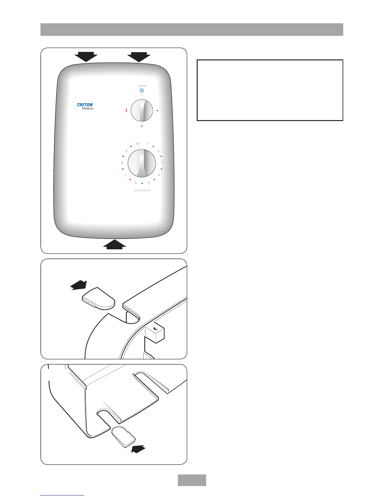
Note: The control knobs are an integral part of
the cover — DO NOT attempt to remove them.
Unscrew the two top and one bottom retaining
screws (fig.6) and lift the cover from the
backplate.
Entry positions for the mains water and electric
cable are from the top, bottom, either side or
from the back.
Note: Deviations from the designated entry
points will invalidate product approvals.
If a bottom entry has been chosen, fit the
appropriate cut-out in the top of the backplate
(fig.7).
If a top entry has been chosen, fit the
appropriate cut-out in the bottom of the cover
(fig.8).
If a side entry is required, the cover will have
to be cut out. Carefully remove the appropriate
area by using a knife or junior hacksaw (fig.9).
If installing a feed pipe from the back or bottom,
the centre of the inlet valve to the wall surface is
20 mm (fig.10).
Note: If entry is from the back, the nut of the
compression fitting will be partially behind the
surface of the wall (fig.10). This area MUST
be left clear when plastering over the pipework
in order to make the nut accessible for future
adjustments.
After choosing the site for the shower, use the
backplate as a template and mark the two fixing
holes (fig.11). Drill and plug the wall.
(An appropriate drill bit should be used. If the
wall is brick, plasterboard or a soft building block,
appropriate wall plugs and screws should be fitted).
Screw the bottom fixing screw into position
FITTING THE SHOWER TO THE WALL
 Loading...