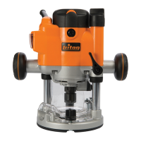
Functions
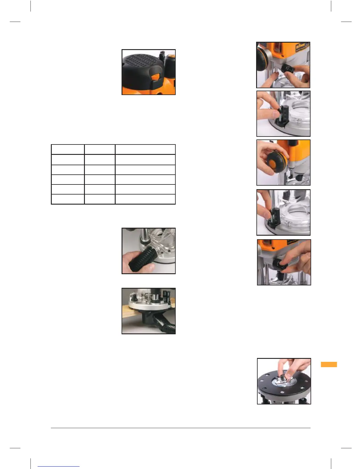
VARIABLE SPEED CONTROL
Router speed settings are not critical
- generally the highest speed which
does not result in burn marks on the
workpiece should be used. Where
stated, always follow the cutter
manufacturer's maximum speed
limitations.
Operating at reduced speed
increases the risk of damage to
the router as a result of overload. Use very slow feed rates and/or
multiple shallow cuts.
The Speed Controller (1) is marked 1 to 5, corresponding
approximately with the speeds and cutter diameters below.
Turn the dial to select the speed.
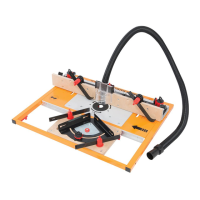
DUST EXTRACTION
Dust Port
The Triton Router is equipped with
a Dust Extraction Port (16) for chip
extraction above the cut. It accepts
38mm (1-½") O.D. hose, supplied
with the Triton Dust Collector
(DCA300).
The hose screws into position via a left hand thread
(anticlockwise).
OPTIONAL CHIP COLLECTOR
ACCESSORY
An optional Dust Chute for effective
chip extraction alongside the cut
zone is available through your local
Triton retailer. It can be connected to
any 38mm (1-½") O.D. hose.
DEPTH STOP & TURRET
• The depth stop and turret enable accurate pre-setting of two
different cut depths in free plunge mode
Setting RPM Cutter Diameter
5 20,000 Up to 25mm (1")
4 18,000 25 - 50mm (1" - 2")
3 14,500 50 - 65mm (2" – 2-
1
⁄2")
2 11,000 Over 65mm (2-
1
⁄2")
1 8,000 Use only if burning
Zeroing the router
1. Fit the router bit you require and
place the router, right side up, on
the work bench
2. Rotate the Turret (9) until the
fixed post is beneath the depth
stop
3. Loosen the Depth Stop Lock
Knob (6) so that the depth
stop is fully released
4. Release the Plunge Lock
Lever (10), then plunge the
router until the tip of the
bit is in contact with the
surface of the work bench
5. Now tighten the Depth Stop
Lock Knob (6) so that the
depth stop is locked in its current
position
Pre-setting the cut depths
1. The top of the fixed post now
provides an accurate datum,
and the depth of cut can be set
by reference to the graduations
printed on the side of the fixed
post
2. To set a cut depth, rotate the
thumbwheel on one of the
Turret Stops (9) until the top of
the thumbwheel aligns with the
depth of cut required (as shown
on the fixed post) For example,
for a cutting depth of 3mm,
rotate the thumbwheel until the
top is aligned with the 3mm
mark on the fixed post. For a
cutting depth of
1
⁄8", rotate the
thumbwheel until the top is
aligned with the
1
⁄8" mark on the
fixed post
3. To pre-set a second depth, repeat the procedure with the
second thumbwheel
Plunging to pre-set depth
• Rotate the turret until the thumbwheel at the required depth is
positioned beneath the depth stop
• Now, when you plunge the router, the depth stop will hit the
thumbwheel and retain the router at the precise depth required
OPTIONAL TEMPLATE GUIDE BUSHES
Different template guide bushes
are available for template routing.
Accessory kits are available through
your local Triton retailer.
330165_Z1MANPRO1(with Japanese).indd 7 21/07/2014 09:49
 Loading...