10
ASSEMBLY STEPS
1. PREPARATION
• Before assembling make sure that you will have enough space around the item.
• Use the supplied parts and hardware for the assembly.
• Before assembling, please check whether all the required parts have been supplied as per the exploded
drawing on the opposite page.
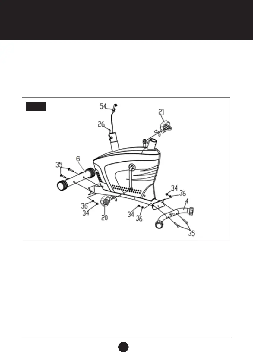
STEP 1: STABILISERS AND PEDAL ASSEMBLY
Attach the Front Stabiliser (Ø50 x 1.5) (6) onto the front curve plate of the Main Frame (1) with 2 Cap
Nuts (M10 x 57 mm) (34), 2 Bolts (M10 x 57) (35) and 2 Big Curved Washers (Ø10) (36).
Attach the Rear Stabiliser (Ø50 x 1.5) (4) in the same manner as the Front Stabiliser (Ø50 x 1.5) (6).
Connect the Left Foot Pedal (YH-30X) (20) to the Left Crank (240J6) (19). Thread it into the crank assembly
in a counterclockwise direction using the tool provided. Connect the Right Foot Pedal (YH-30X) (21) to the
Belt Pulley with Crank (240J6) (19) by threading it in a clockwise direction.
NOTE: The Left and Right Foot Pedals (20, 21) and Belt Pulley with Crank (240J6) (19) are marked with
“L” & “R” (left and right).
STEP 1