B
e
e
F
F
G
G
c
c
U
1562-7
ASSEMBLY STEPS
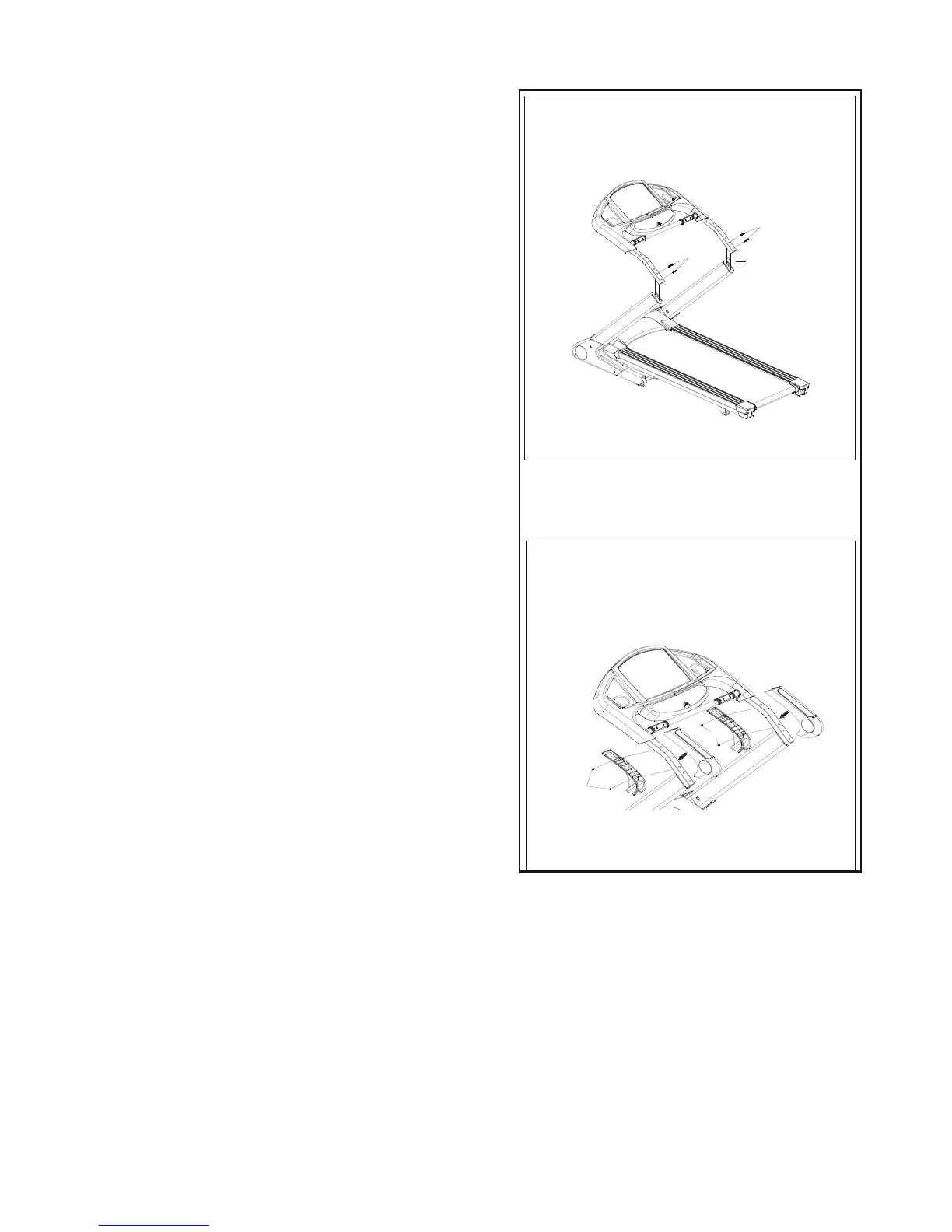
STEP 3
• Connect Control Wire (L) in right Upright (C)
with control wire (U) of Computer Console(A).
• Thread wires into Upright (C,D) and place Computer
Console(A) on the Frame.
• Attach with Allen Bolt (d).
CAUTION:
Ensure that cables are not damaged during assembly or when
tightening screws.
STEP 4
• Attach upper and lower Handrail Covers (E, F), to Handrail.
• Attach them with Self Tapping Screw (b).
CAUTION:
Ensure that cables are not damaged during assembly or when
tightening screws.